Corne LP Build Guide
Assembling a Corne LP keyboard, from components to complete
[ Updated 06-25-22 | Created 09-02-21 ]
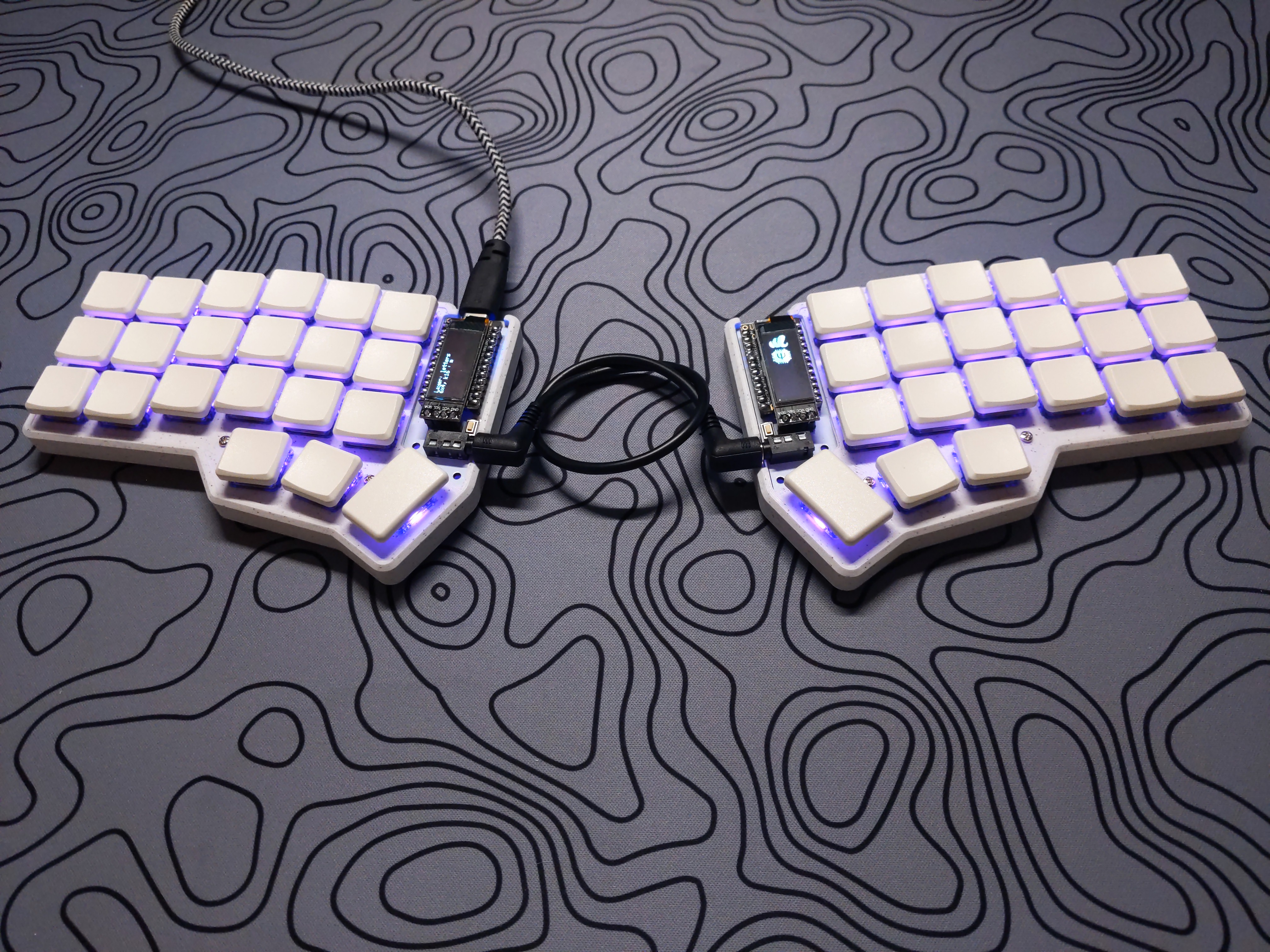
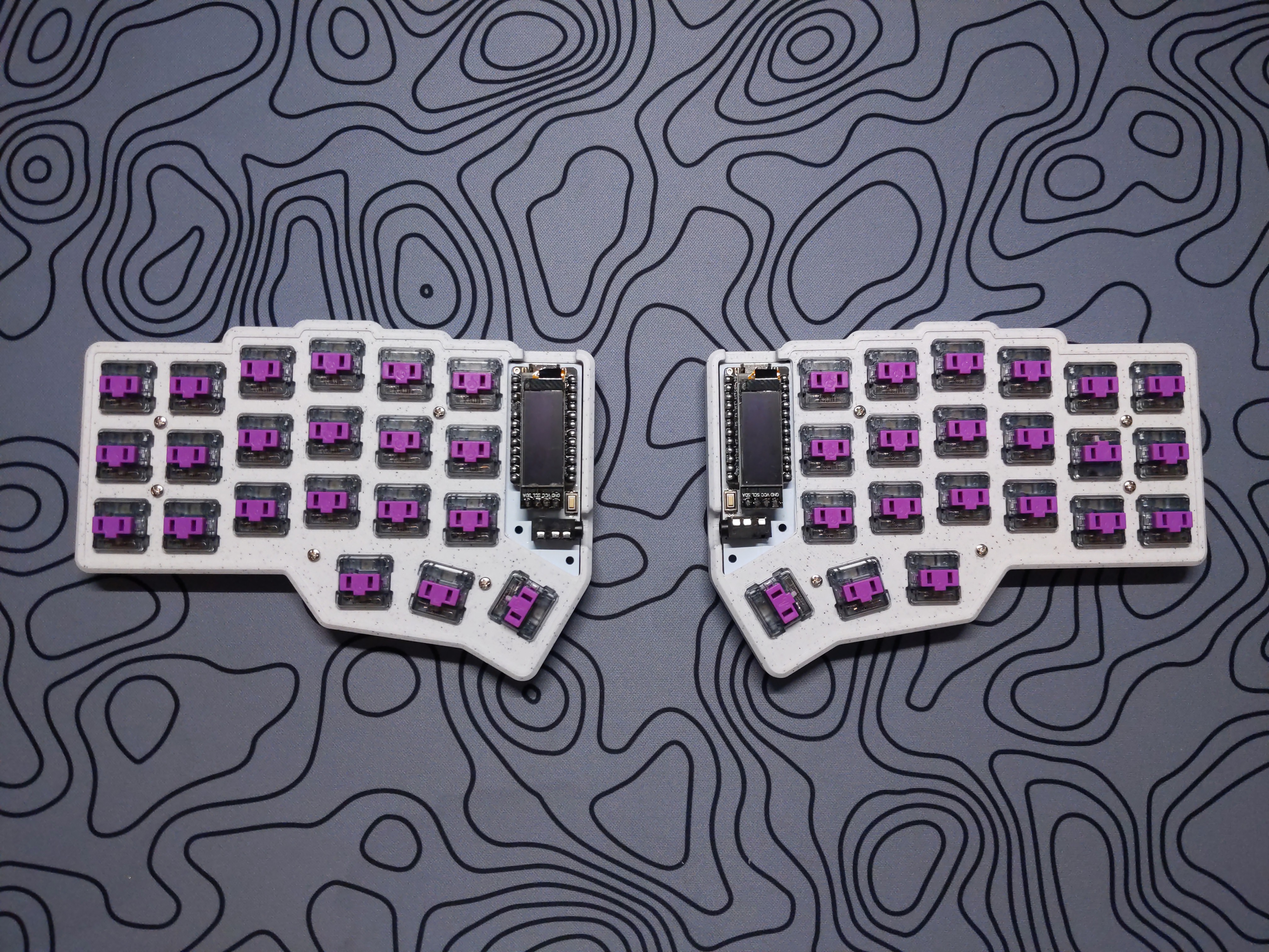
The Corne keyboard is a split keyboard with 3x6 column staggered keys and 3 thumb keys, based on Helix. Crkbd stands for Corne Keyboard.
Table of Contents
Parts
Bill of Materials
| Part | Qty |
|---|---|
| Corne Chocolate PCB | 2 |
| Corne Chocolate Case/Plate Kit | 1 |
| Pro Micro (or equivalent) | 2 |
| Pro Micro Millmax Sockets (1x12) | 4 |
| Pro Micro Millmax Pins | 48 |
| TRRS Jack | 2 |
| TRS/TRRS Cable | 1 |
| Reset Button | 2 |
| Kailh Choc Hotswap Socket | 42 |
| SMD Diode (1N4148) | 42 |
| Per-key SMD LED (SK6812Mini-E) | 42 |
| Underglow SMD LED (WS2812B) | 12 |
| 128x32 OLED Display | 2 |
| OLED Millmax Sockets (1x4) | 2 |
| OLED Millmax Pins (1x4) | 2 |
| Choc-Compatible Switch | 42 |
| 1U Choc-Compatible Keycap | 40 |
| 1.5U Choc-Compatible Keycap | 2 |
Kits
Boardsource - Corne LP (featured)
LittleKeyboards - Corne Choc Hotswap PCB Kit
Ookami Keyboards - 3D Printed Corne Low Profile Case (featured)
Other vendors offer similar kits, but I have opted to only list vendors I frequent as I can vouch for their quality and customer service.
Assembly
PCB Overview

42 diodes are located to the left of each switch hole.
42 per-key LEDs are located above each switch hole. 12 additonal underglow LEDs are placed around the back of the PCB.
42 sockets are located below each switch hole.
The microcontroller and OLED socket holes are soldered from the back of the PCB.
The TRRS jacks and reset buttons are soldered from the back of the PCB.
Diodes

Diodes are soldered to two pads.
Ensure the vertical line on the diode aligns with the vertical line on the PCB!
Tin one of the pads, then hold the iron to the joint while placing the diode leg on the pad. Solder the remaining diode leg to the second pad.
LEDs

Per-key LEDs are soldered to four pads.
Ensure the notched LED leg aligns with the corner printed on the PCB!
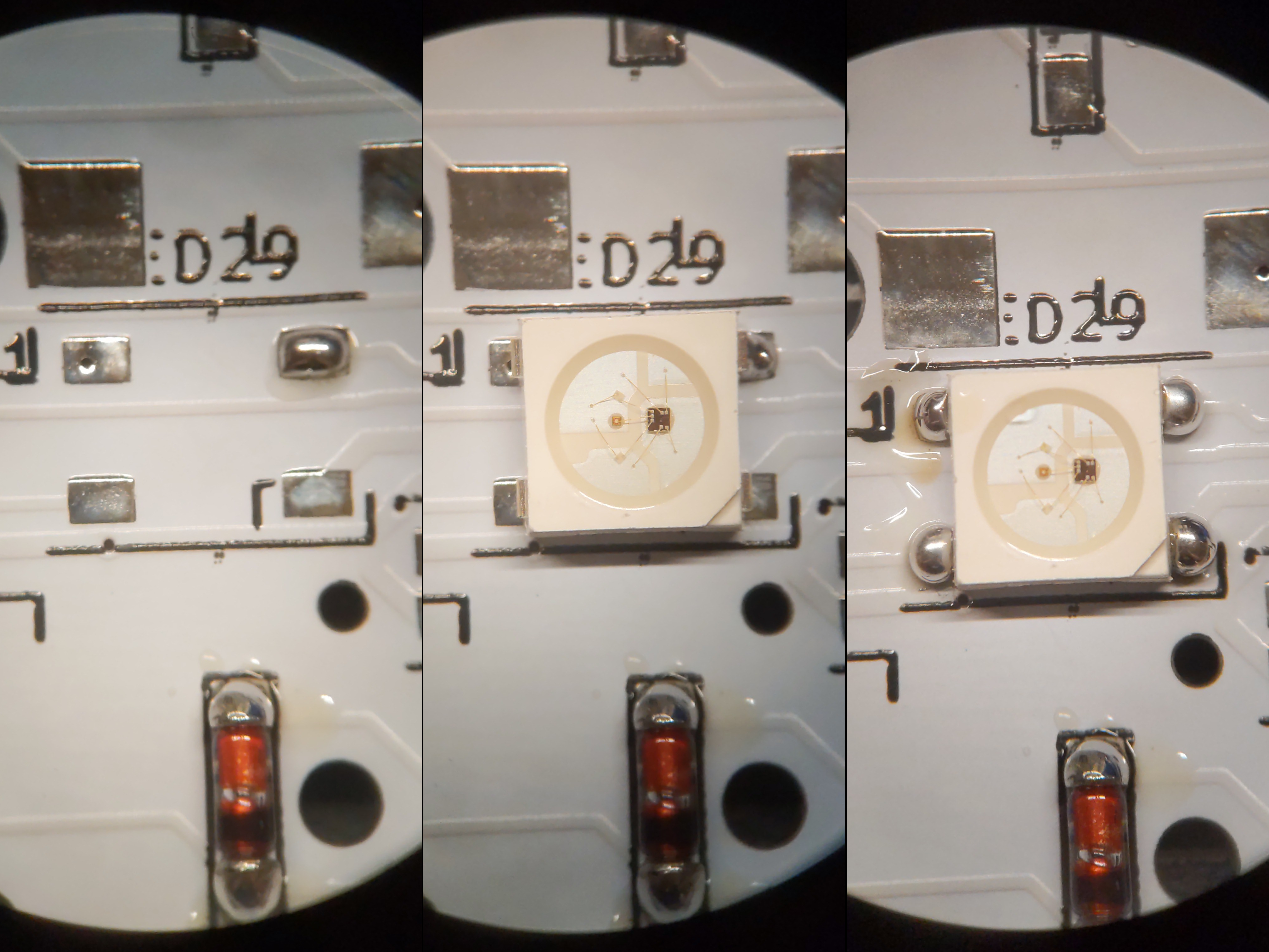
Underglow LEDs are soldered to four pads.
Ensure the notched corner of the LED aligns with the corner printed on the PCB!
Tin one of the four pads, then hold the iron to the joint while placing the LED leg on the pad. Solder each remaining LED leg to its respective pad.
Sockets
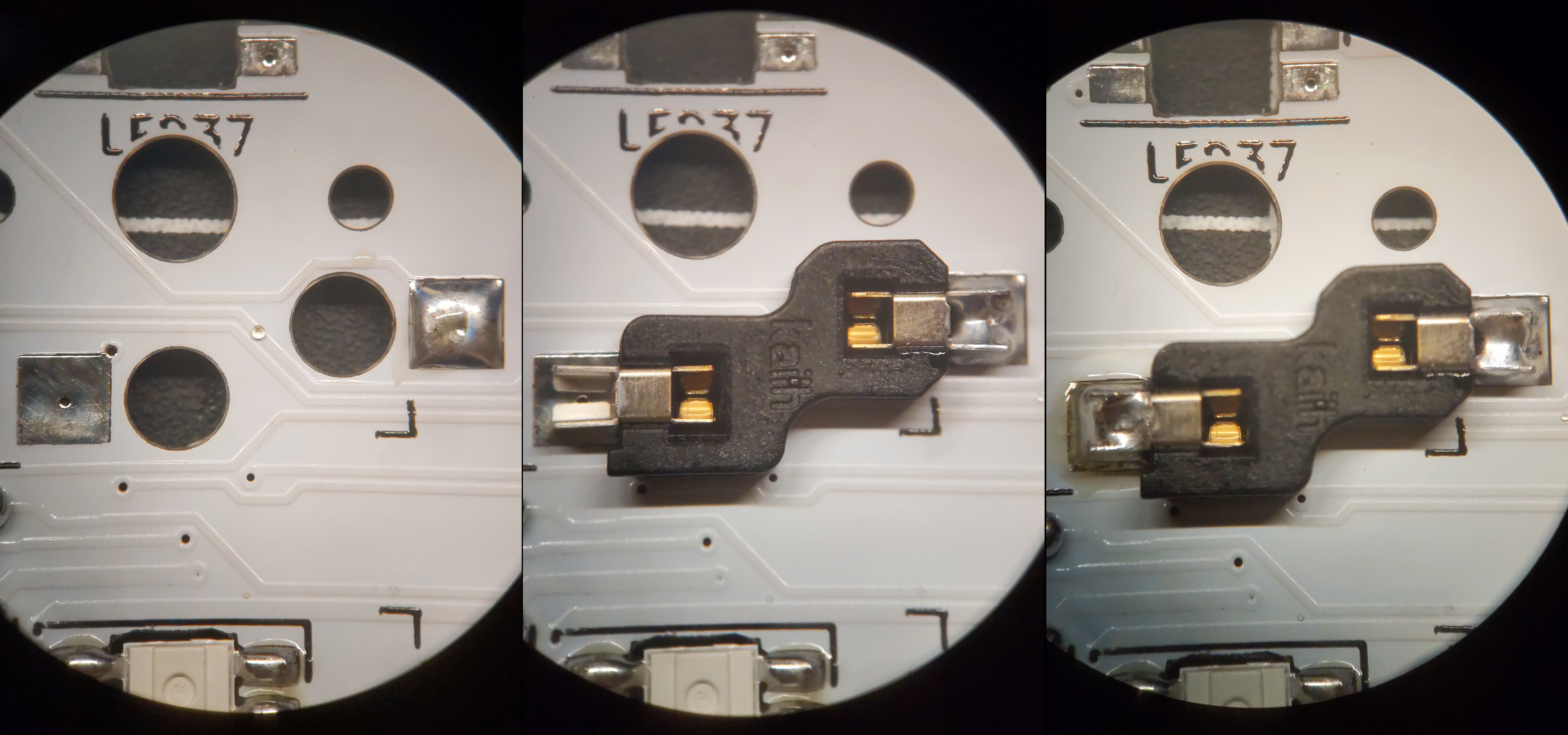
Sockets are soldered to two pads.
Tin one of the pads. While resting the socket leg over the pad, hold the iron to the joint and apply some pressure. Solder will begin to flow through the small crack in the socket leg and bury it in the joint. Apply a generous amount of solder to the second pad. Now that the socket is seated, apply a bit more solder to the first pad.
Microcontroller
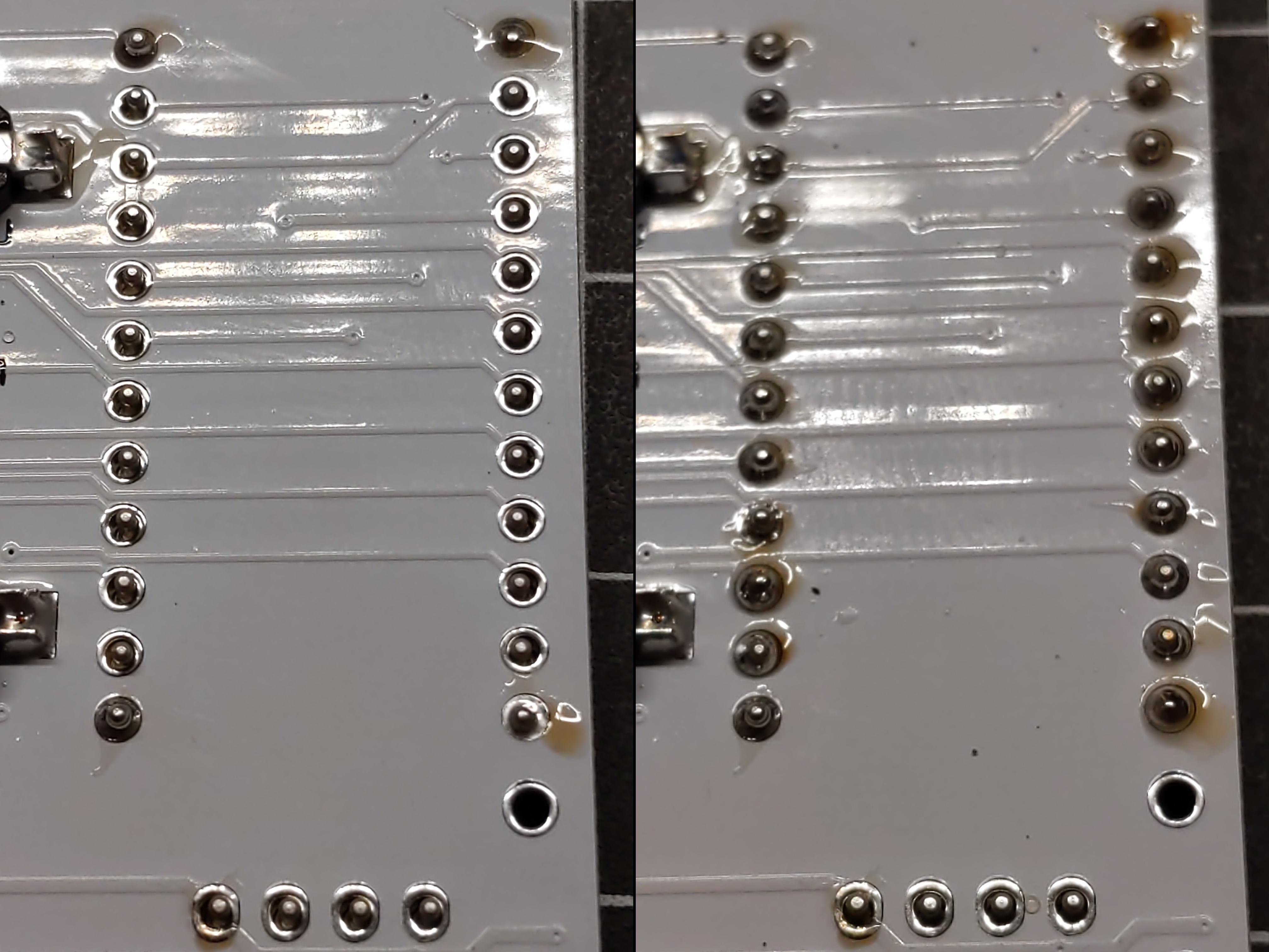
Flash the firmware to verify the microcontroller works before soldering it!
The microcontroller is soldered to pin sockets. If unsocketable pins were included with the microcontroller, do not use them.
Place each row of sockets on the front of the PCB. Flip the PCB over and solder the sockets pin by pin. If the sockets fall out during the process, use electrical tape or similar to secure them from the front of the PCB. Start by soldering the top and bottom pins of each row to the PCB ensuring the socket remains flush with the PCB. Once both rows have been soldered, flip the PCB over again and insert one pin into each socket. OLED pins will be soldered in a later step.
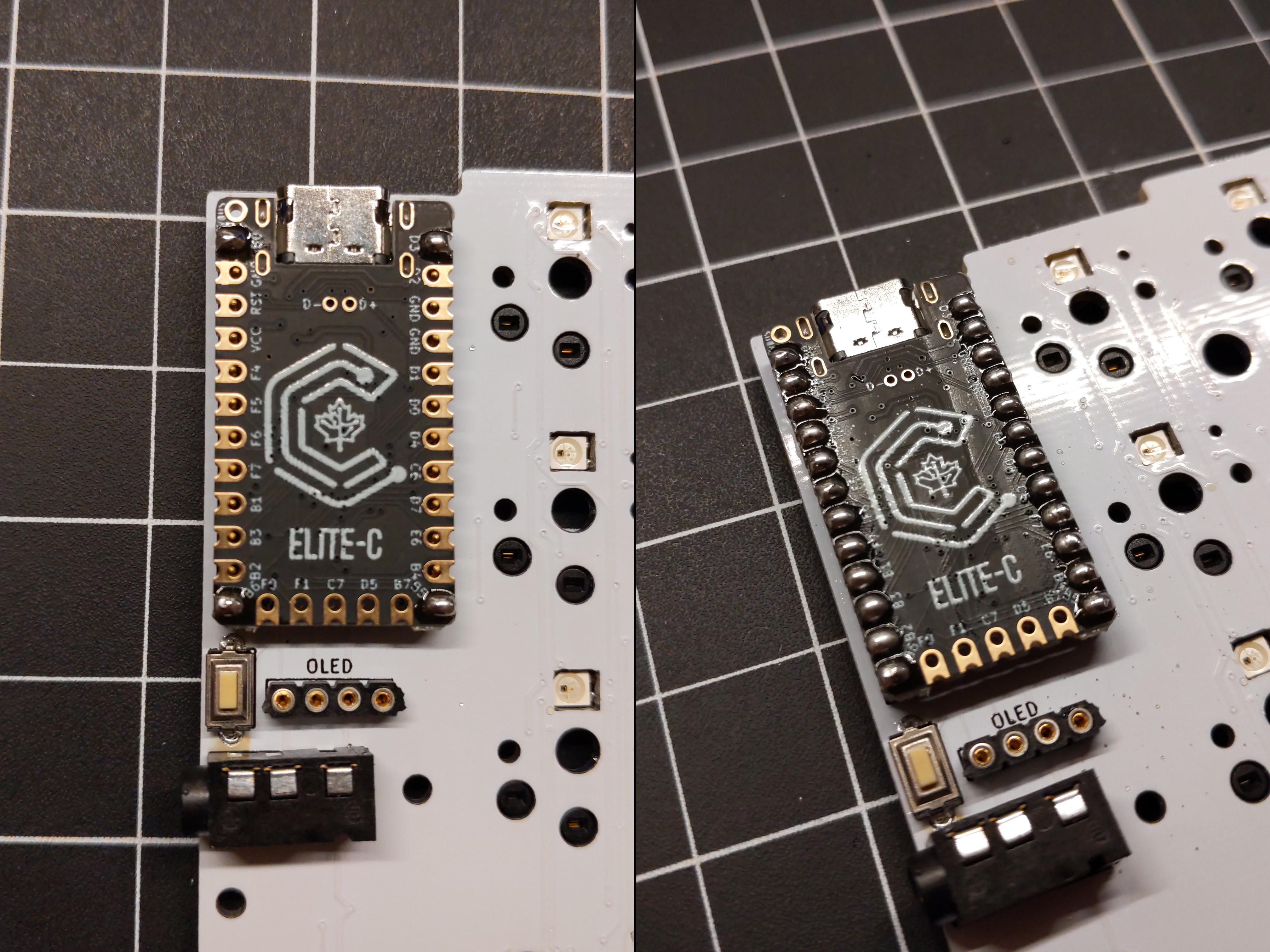
Place the microcontroller face-down on top of the pins. Start by soldering the top and bottom pins of each row to the microcontroller. Continue to solder each pin ensuring no two joints connect with one another.
OLEDs
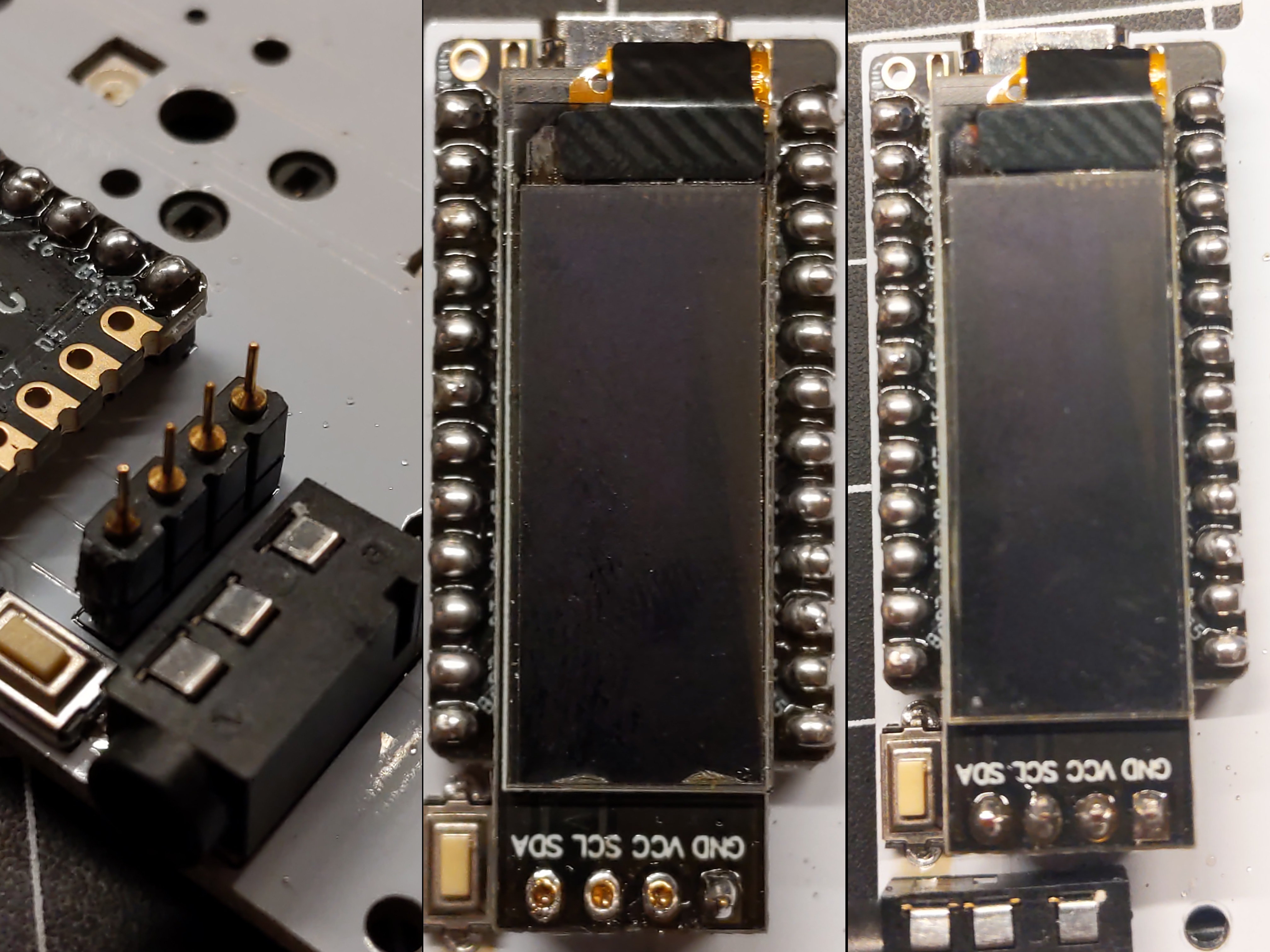
The OLED is soldered to pin sockets. If unsocketable pins were included with the display, do not use them.
Place the OLED pins in the OLED socket, verifying they sit flush with the sockets. Place the OLED display screen-up on top of the pins. Start by soldering one of the four pins. To achieve a straight and level display, carefully hold the OLED while soldering so the display is not leaning left/right and is not tilting up/down. Solder the remaining pins while continuing to adjust the display to prevent leaning and tilting. Ensure no two solder joints connect with one another.
TRRS/Reset
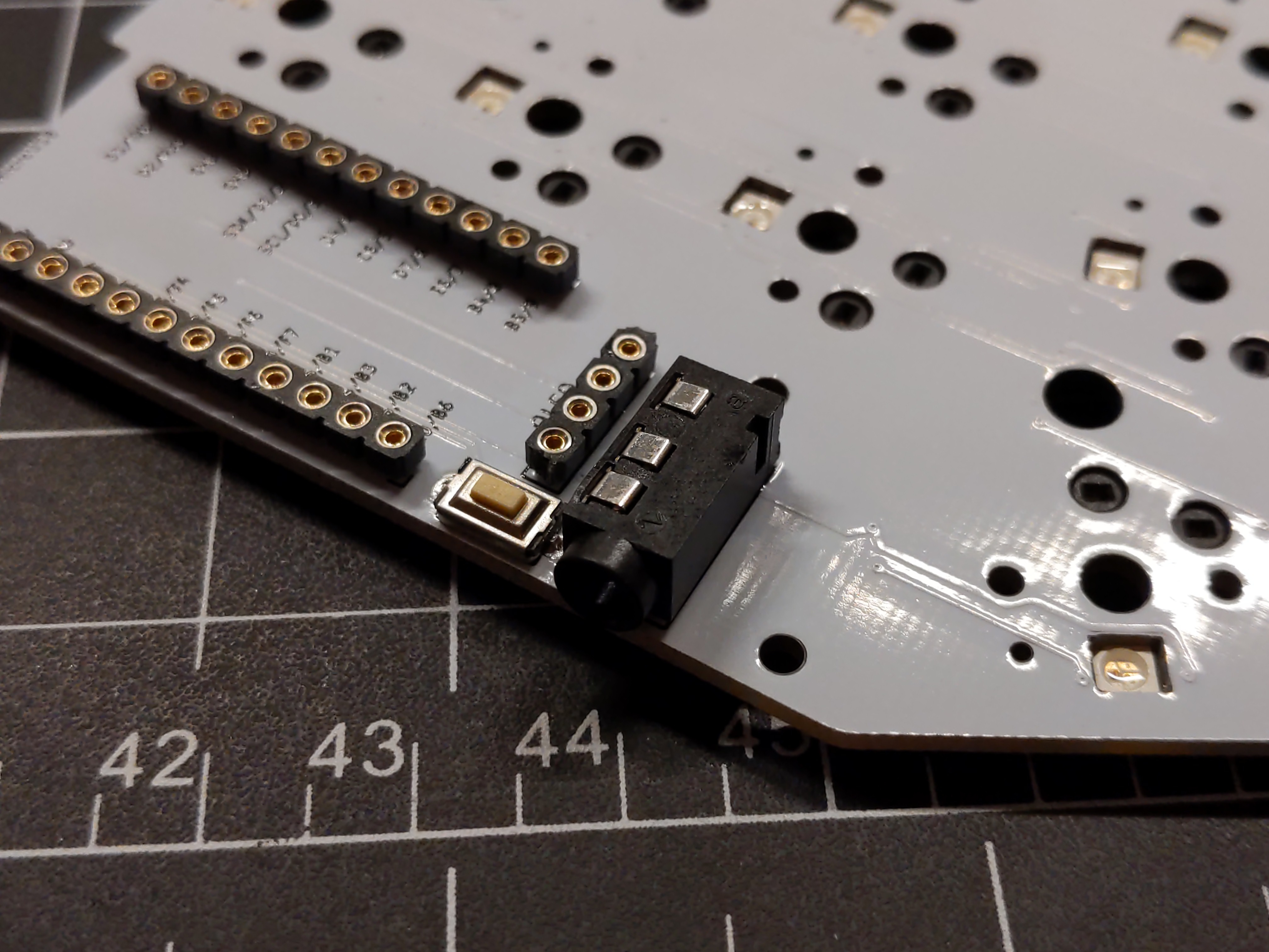
The reset button is soldered to the front of the PCB. Place each leg into the hole soldering one at a time. Optionally, more solder can be added to the joints from the back of the PCB.
The TRRS jack is soldered from the back of the PCB. Place the jack on the front of the PCB and solder each leg from the back of the PCB. If the jack falls out during the process, use electrical tape or similar to secure it to the front of the PCB. Ensure the jack is reasonably straight and not crooked.
Case
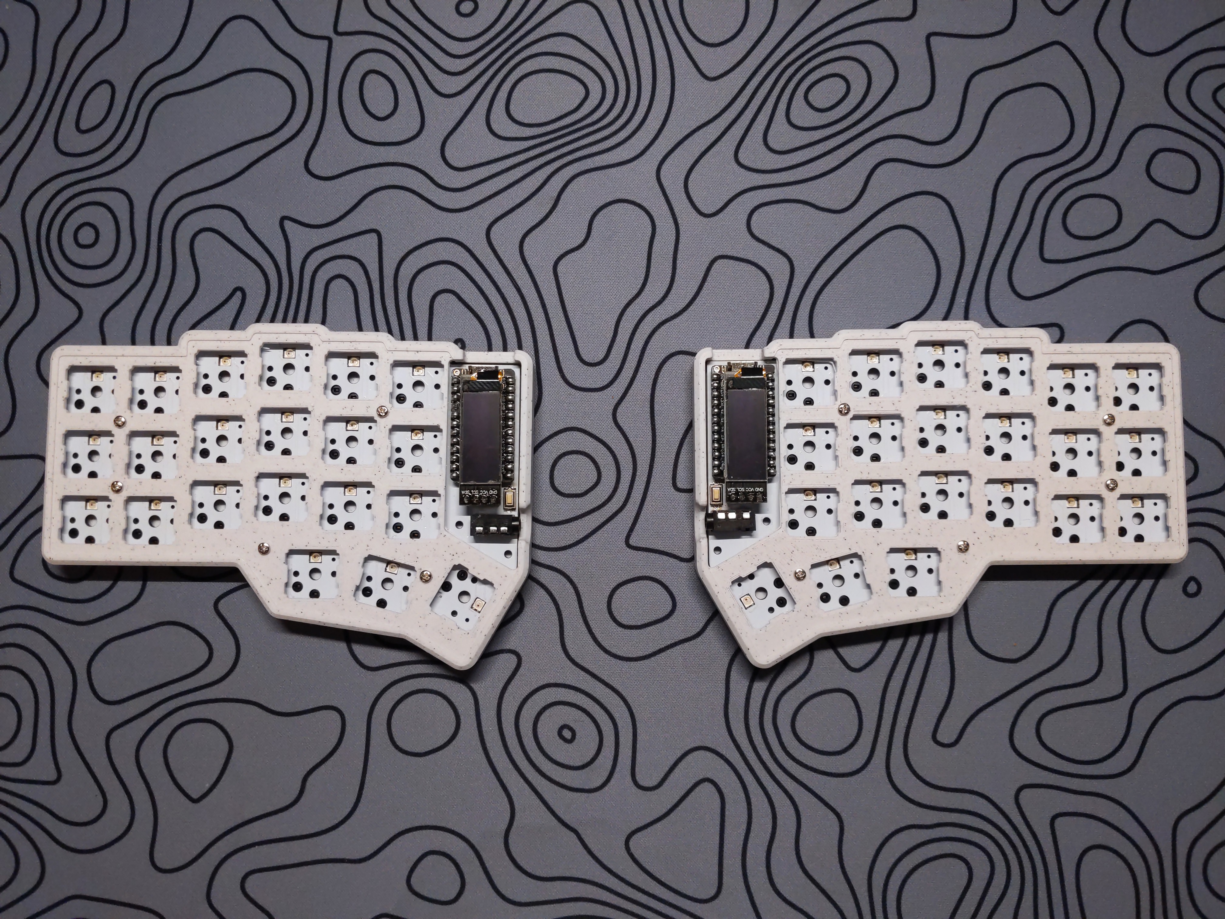
Case assembly varies by case type. The PCB is sandwiched between the top and bottom plates/cases. If applicable, install the OLED cover standoffs before assembling the PCB in the plates/case.
Switches
Insert 42 Choc-compatible switches into the hotswap sockets.
Firmware
Customization
The easiest way to create a custom keymap is via QMK Configurator, a graphical web-based editor. Advanced users can manually create a keymap to compile and flash with QMK command-line tools.
More information can be found in the QMK Docs or QMK Discord.
Flashing
See QMK Docs: Flashing Firmware for platform-specific instructions.