Osprette Build Guide
Assembling an Osprette keyboard, from components to complete
[ Updated 06-25-22 | Created 12-11-21 ]
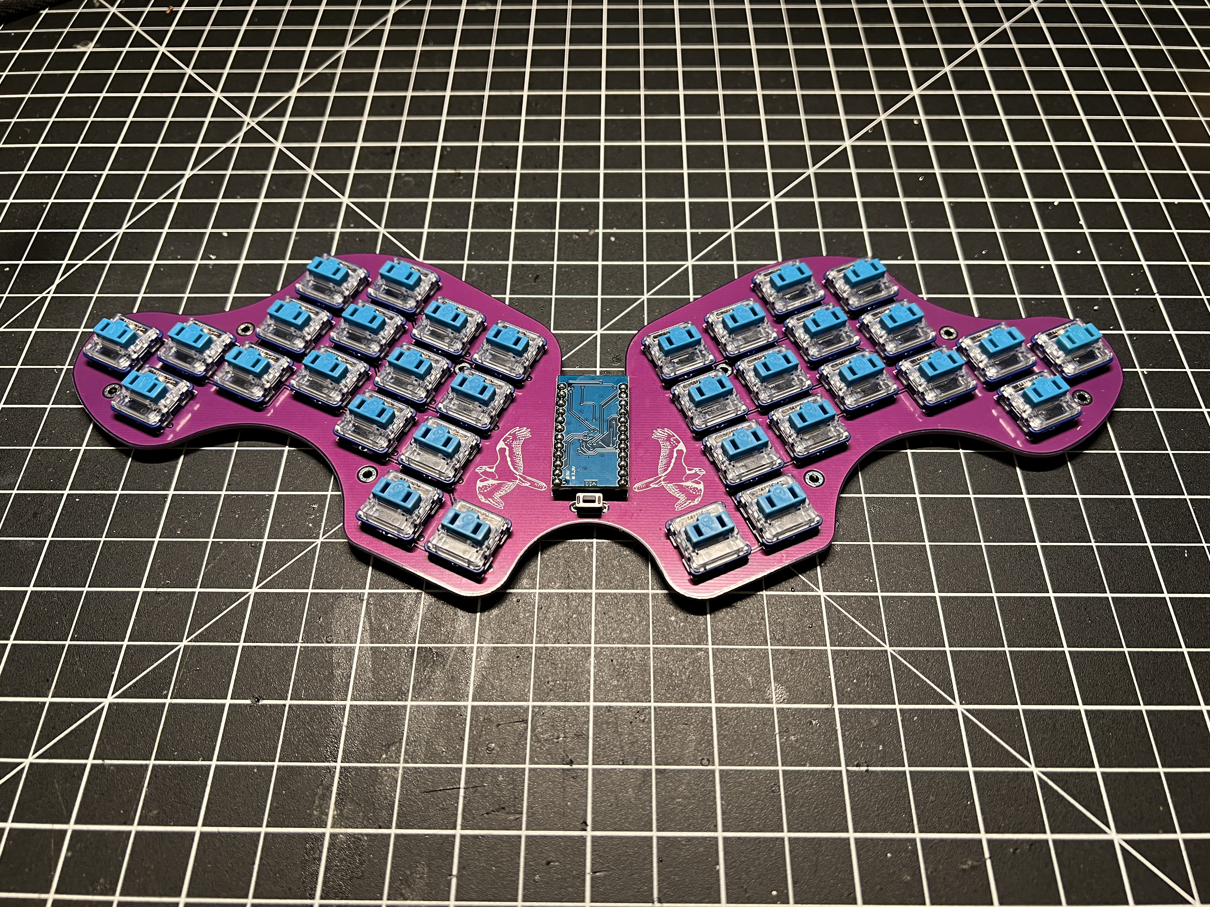
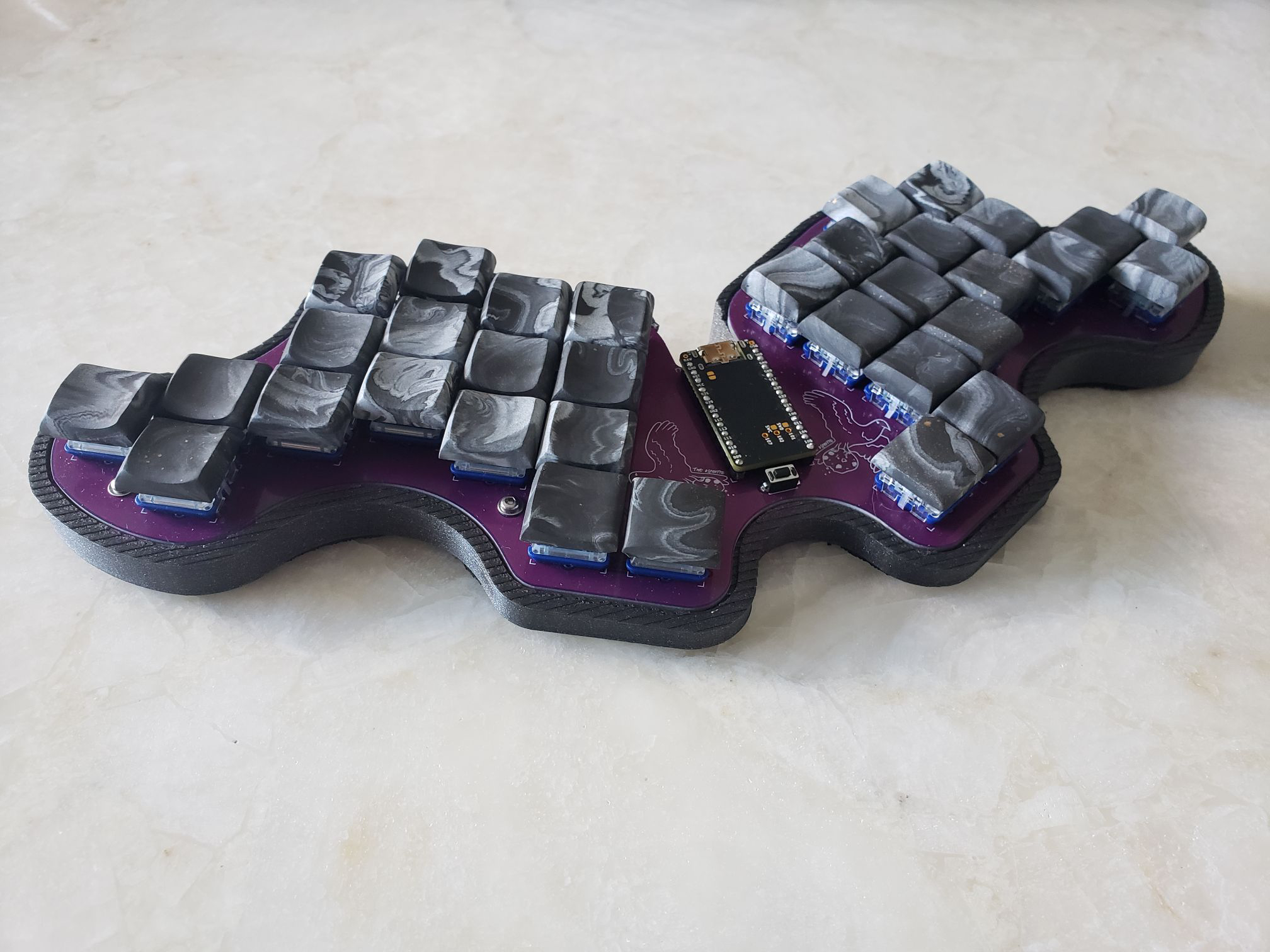
The Osprette is a 34-key low profile keyboard designed by Sam Mohr.
Table of Contents
Parts
Bill of Materials
| Part | Qty | Vendor |
|---|---|---|
| MCU (Pro Micro compatible) | 1 | AliExpress |
| SMD diodes | 34 | AliExpress |
| Reset switch | 1 | Digi-Key |
| Power switch (optional, wireless only) | 1 | Digi-Key |
| Choc v1 switches | 34 | MKUltra |
| Choc v1 keycaps | 34 | MKUltra |
| Choc hotswap sockets (optional) | 34 | Adafruit |
| Low-profile controller sockets/pins | 2 | LittleKeyboards |
| M2 9mm screws (for case) | 8 | AliExpress |
| M2 nuts (for case) | 8 | AliExpress |
Assembly
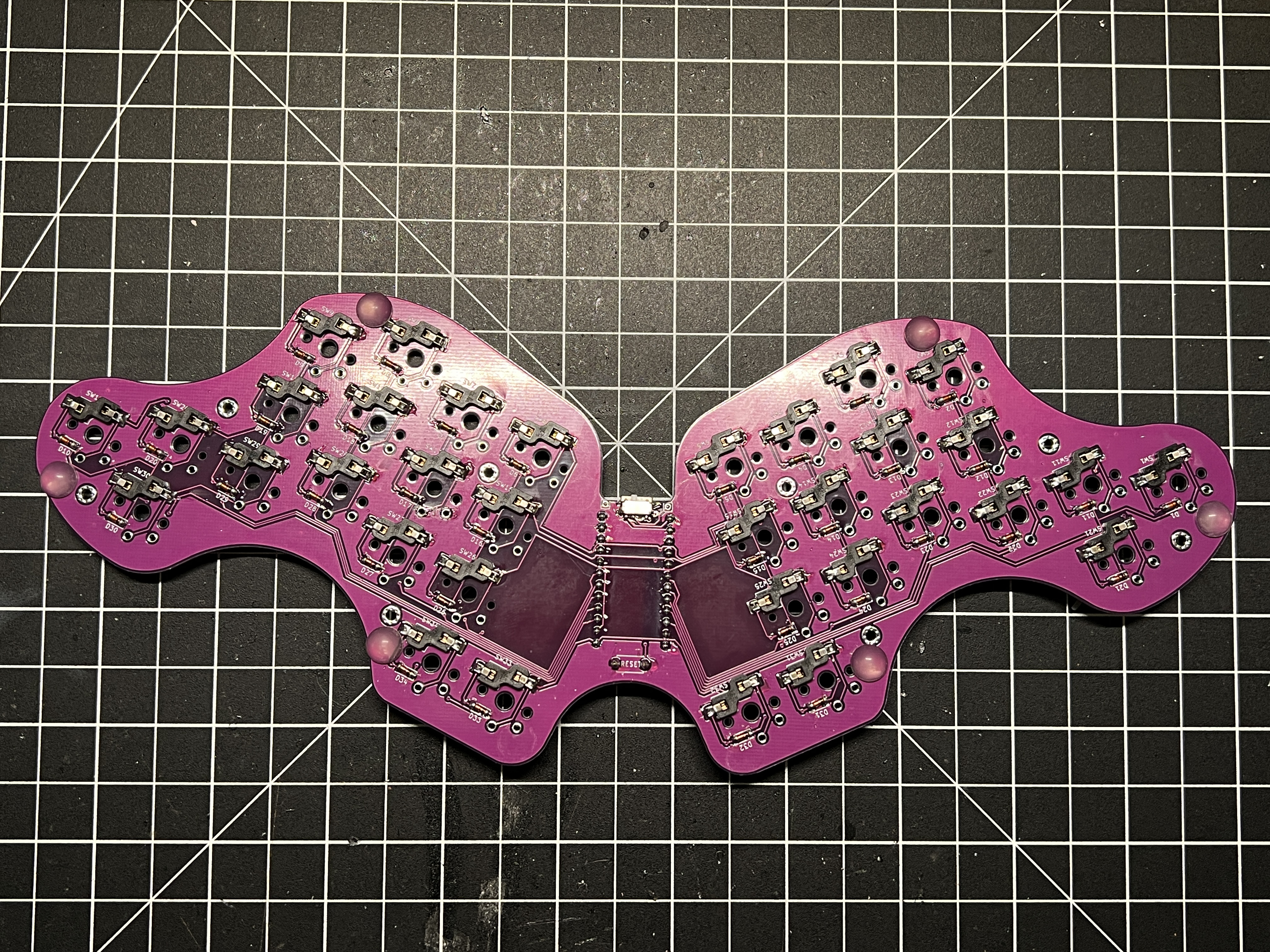
PCB Overview
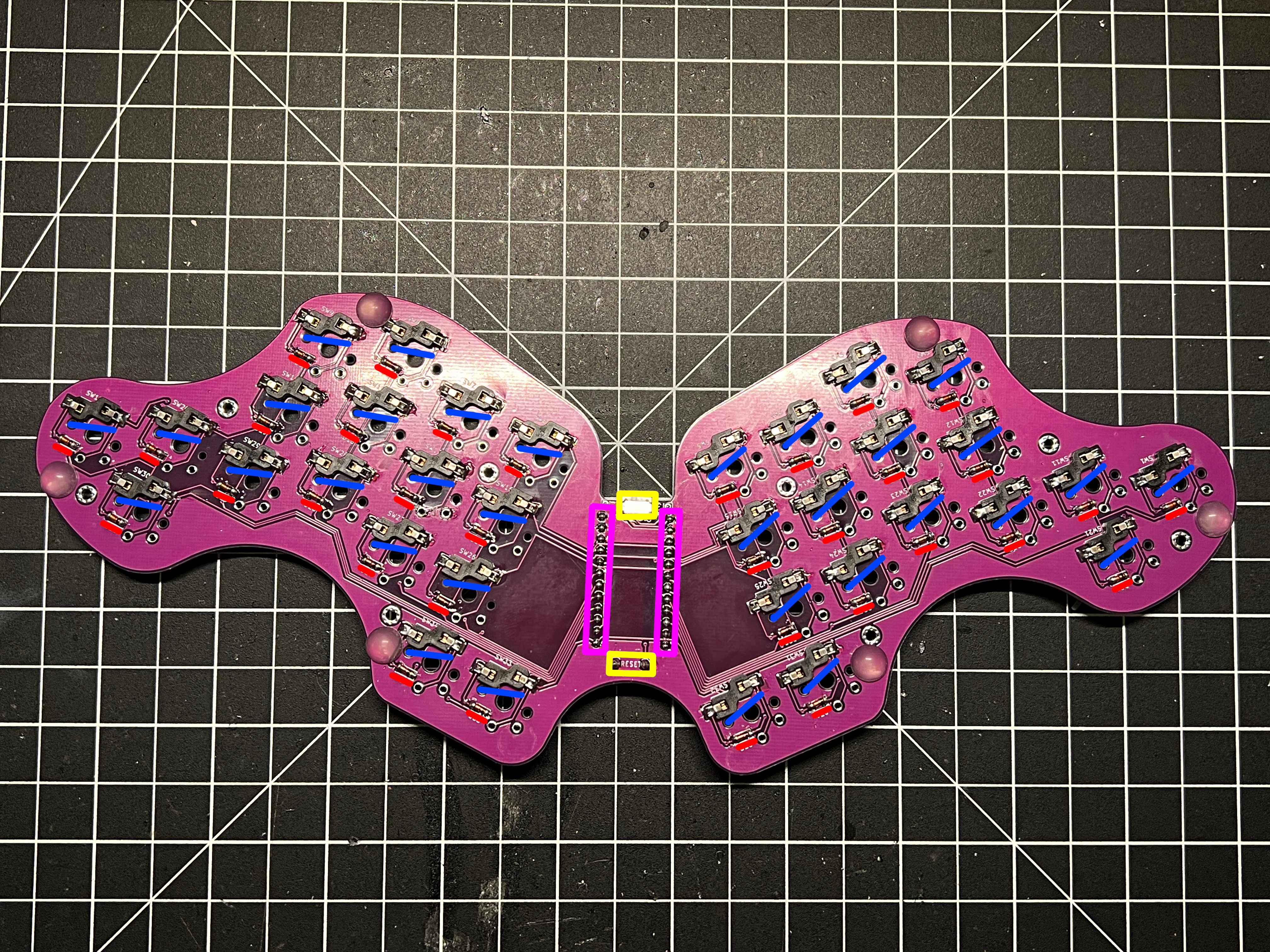
34 diodes are located on the back of the PCB below each switch hole.
34 sockets are located on the back of the PCB above each switch hole.
The microcontroller socket holes are soldered on the back of the PCB.
The reset button socket holes are soldered on the front of the PCB with the button facing downwards.
The optional power switch is located on the back of the PCB.
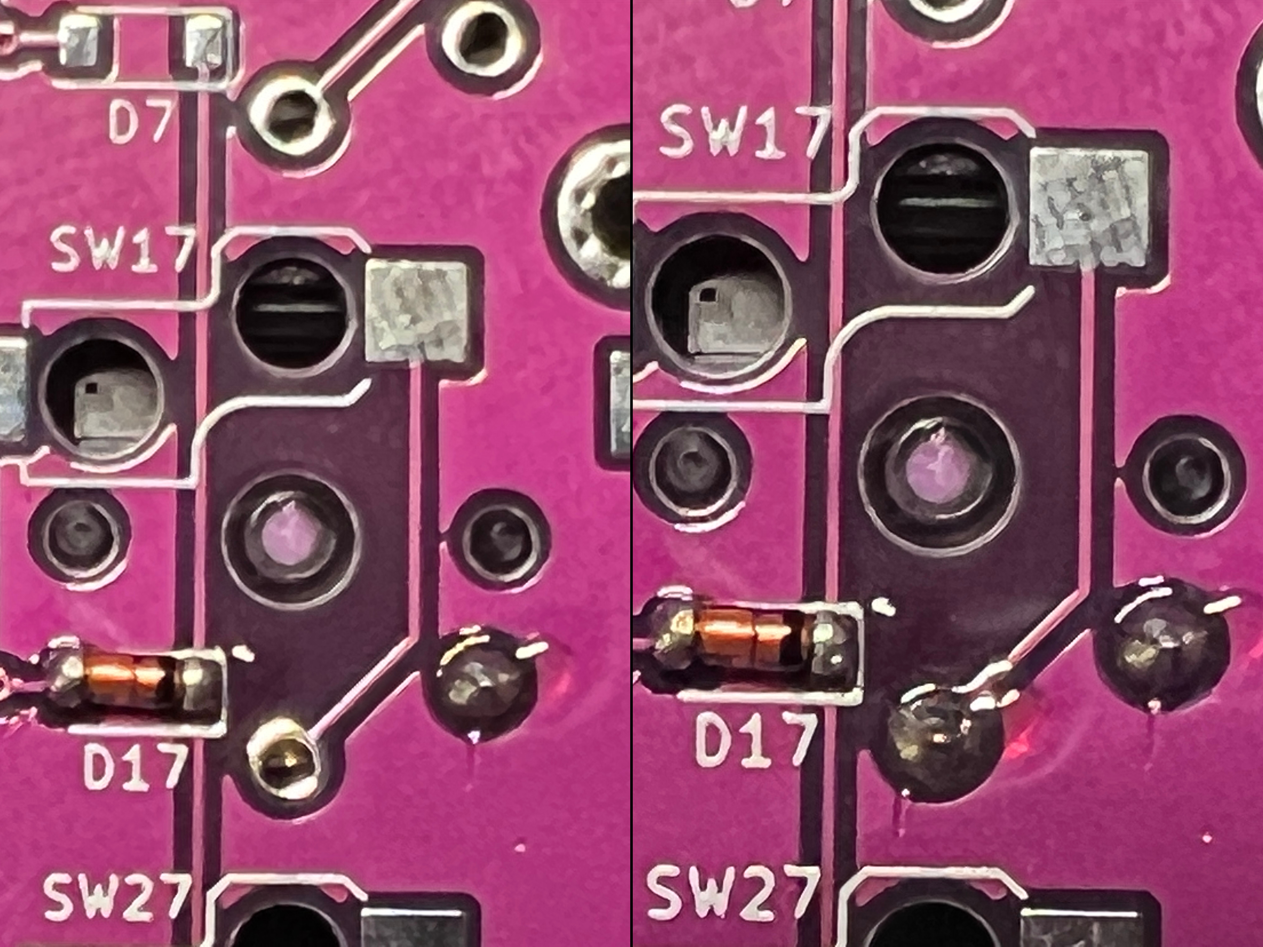
Diodes
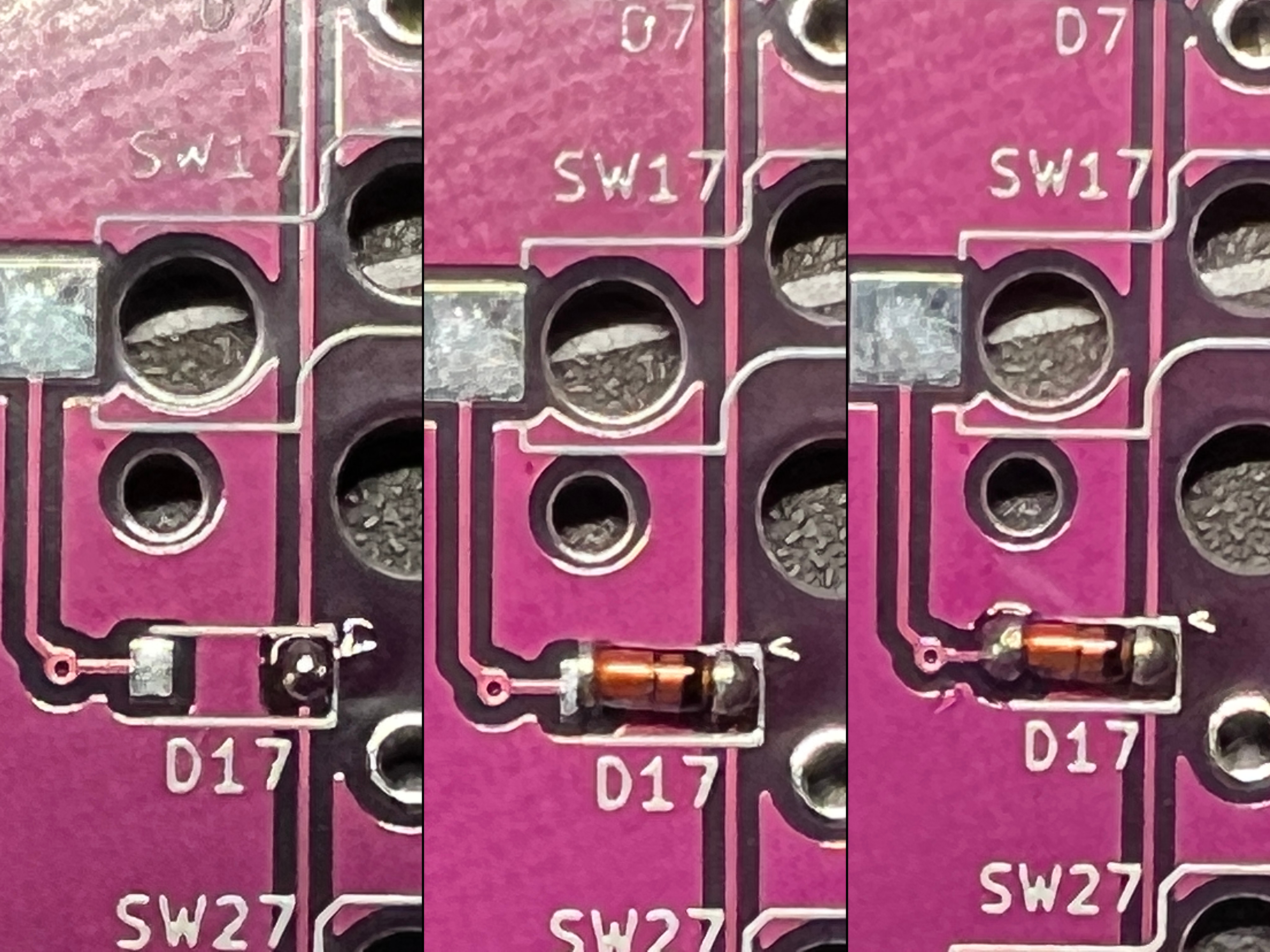
Diodes are soldered to two pads.
Ensure the black line on the diode is facing the white line (right) on the PCB silkscreen!
Tin one of the pads, then hold the iron to the joint while placing the diode leg on the pad. Solder the remaining diode leg to the second pad.
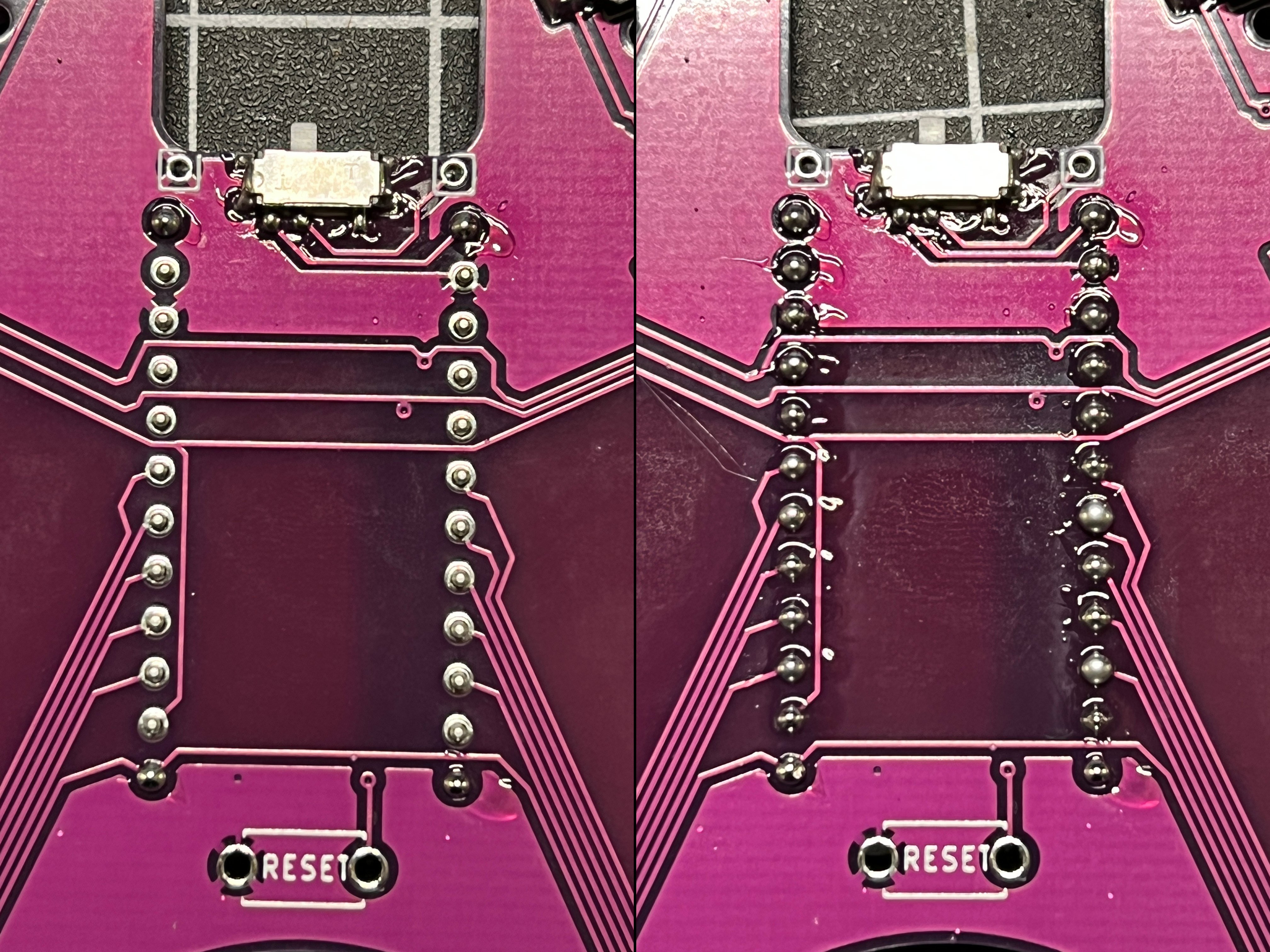
Sockets (Option 1)
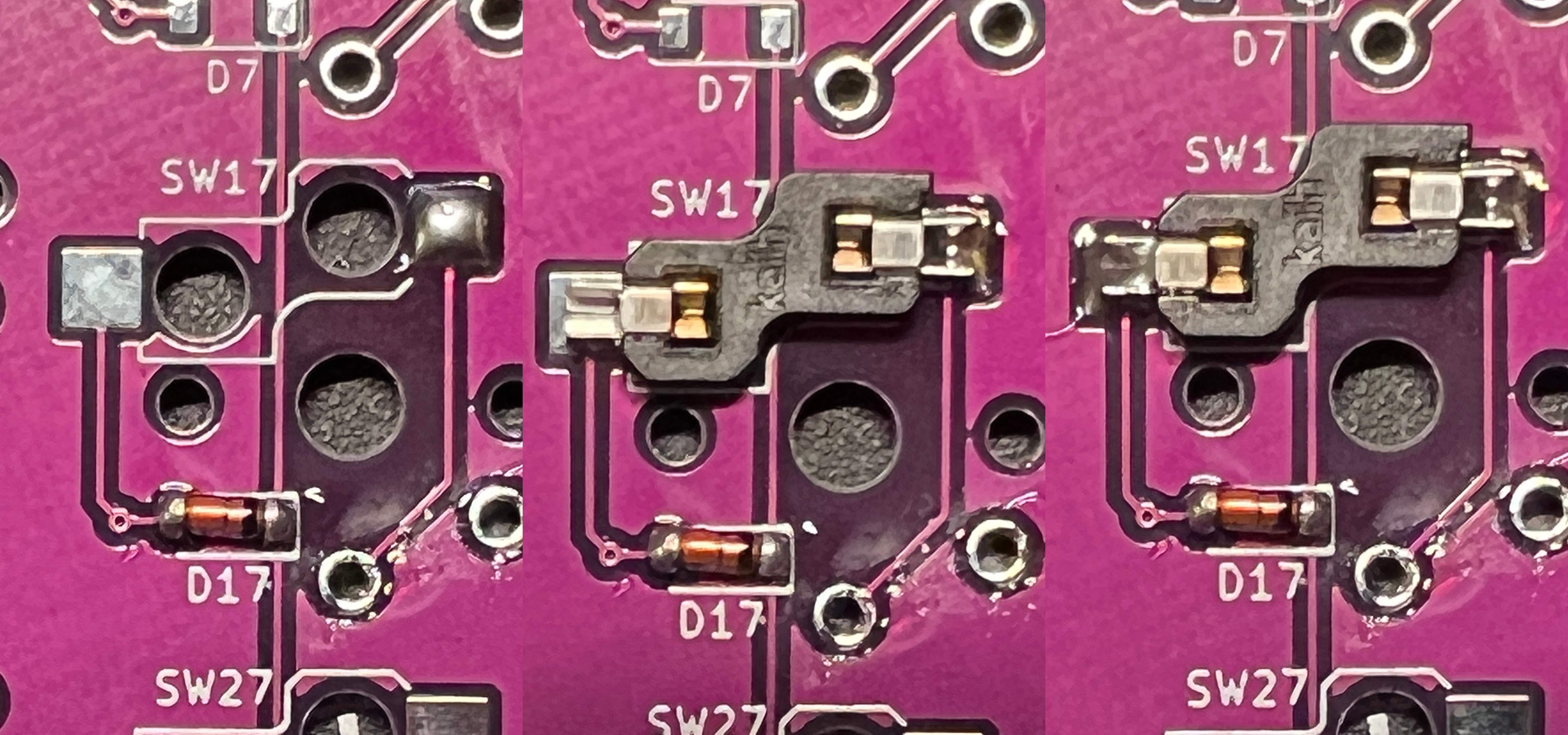
Sockets are soldered to two pads.
Tin one of the pads. While resting the socket leg over the pad, hold the iron to the joint and apply some pressure. Solder will begin to flow through the small crack in the socket leg and bury it in the joint. Apply a generous amount of solder to the second pad. Now that the socket is seated, apply a bit more solder to the first pad.
Switches (Option 2)
Switch legs are soldered to two through-hole pads in the absence of hotswap sockets.
Insert the switch from the front of the PCB ensuring it is fully seated and that both legs stick through their respected holes. Apply solder to each leg until each through-hole is filled.
Microcontroller
Flash the firmware to verify the microcontroller works before soldering it!
The microcontroller is soldered to pin sockets. If unsocketable pins were included with the microcontroller, do not use them.
Place each row of sockets on the front of the PCB. Flip the PCB over and solder the sockets pin by pin. If the sockets fall out during the process, use electrical tape or similar to secure them from the front of the PCB. Start by soldering the top and bottom pins of each row to the PCB ensuring the socket remains flush with the PCB. Once both rows have been soldered, flip the PCB over again and insert one pin into each socket.
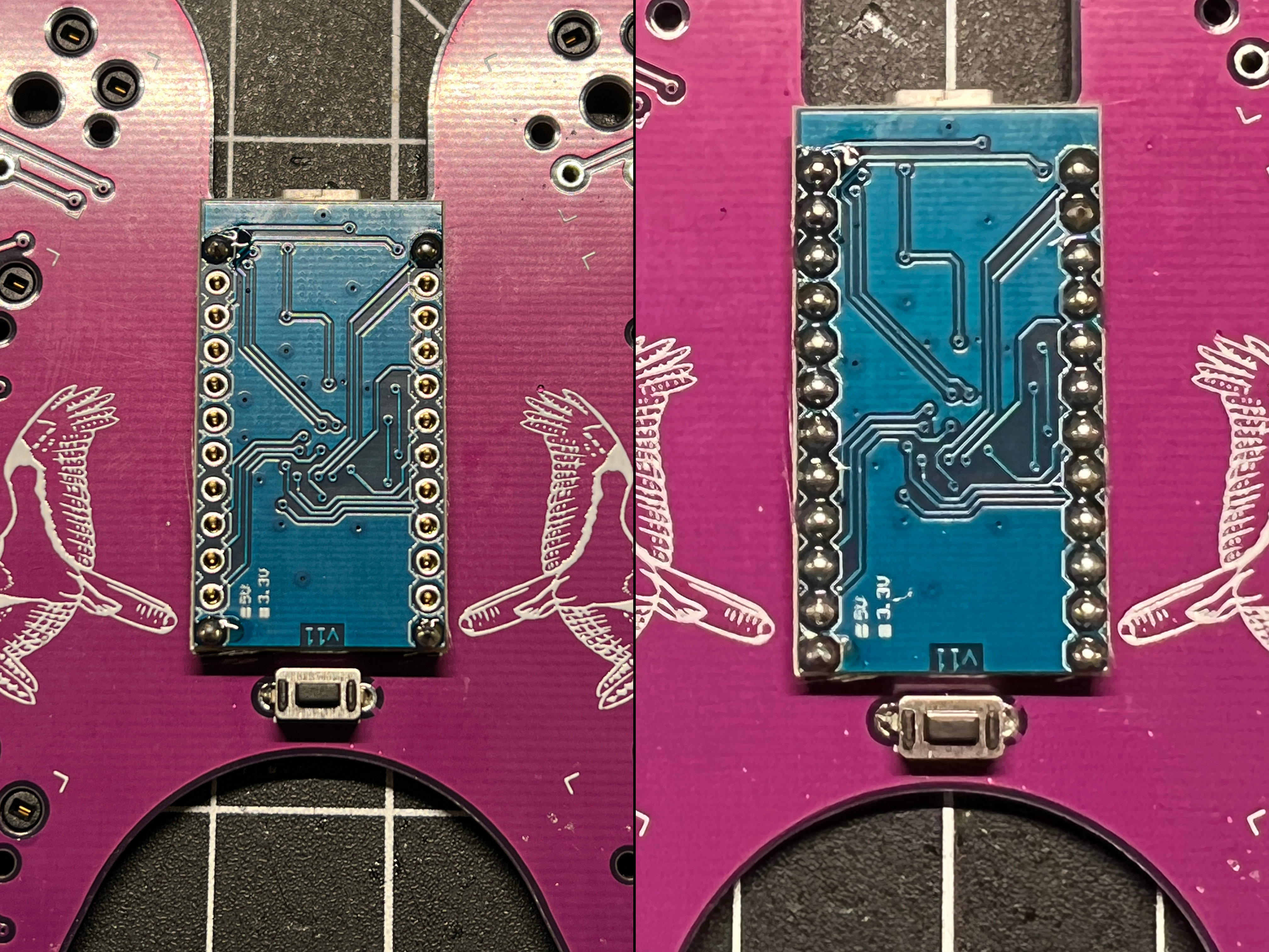
Place the microcontroller face-down on top of the pins. Start by soldering the top and bottom pins of each row to the microcontroller. Continue to solder each pin ensuring no two joints connect with one another.
Buttons

The reset button is soldered from the back of the PCB. Place each leg into the hole soldering one at a time.
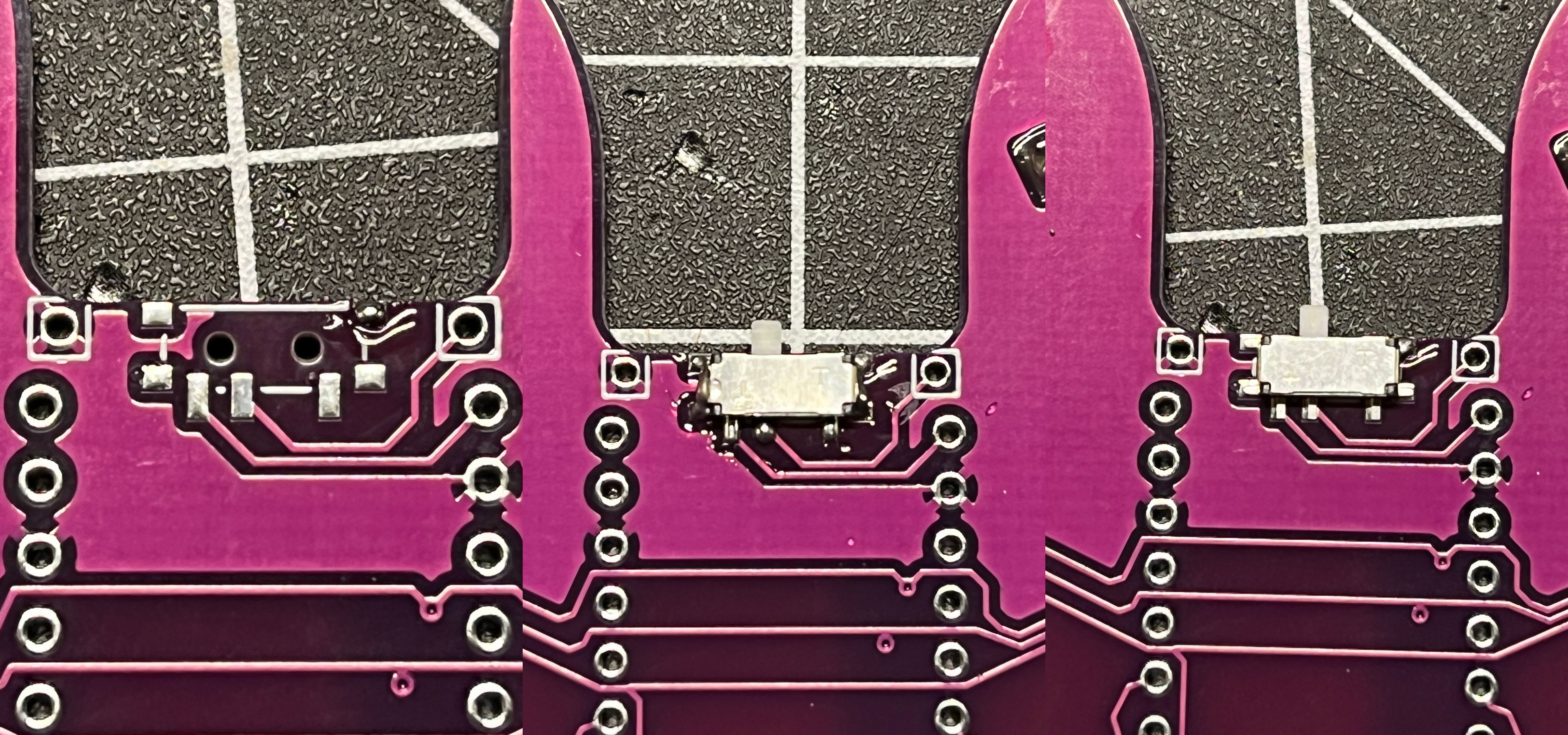
The optional power switch is soldered on the back of the PCB. Tin one of the seven pads, then hold the iron to the joint while placing the switch leg on the pad. Solder each remaining switch leg to its respective pad.
Case
The 3D-printed case can be downloaded here.
Place the PCB into the 3D-printed base and secure it with screws.
If you do not want a 3D-printed case, tall rubber bump-ons can be added to the bottom of the PCB.
Firmware
Customization
Firmware can be found in Sam Mohr’s QMK fork. Clone his fork or download the linked files and place them in a local QMK folder (/qmk_firmware_keyboards/osprette). The default keymap is found in the keymaps folder per usual.
More information can be found in the QMK Docs or QMK Discord.
Flashing
See QMK Docs: Flashing Firmware for platform-specific instructions.