Reviung41 Build Guide
Assembling a Reviung41, from components to complete
[ Updated 06-25-22 | Created 08-04-21 ]
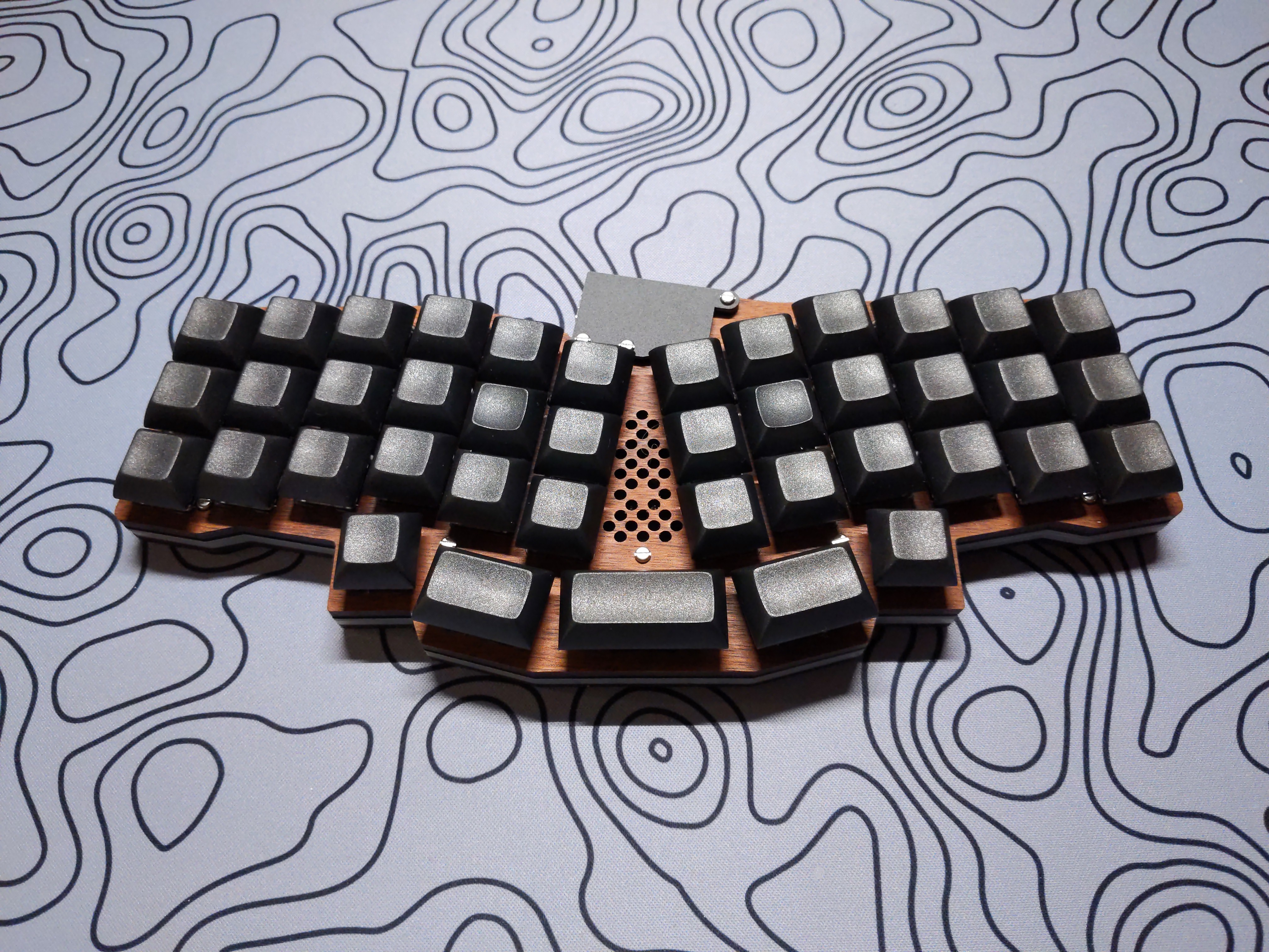
The Reviung41 is a 41-key column staggered keyboard designed by gtips.
Table of Contents
Parts
Bill of Materials
| Part | Qty |
|---|---|
| Reviung41 PCB | 1 |
| Reviung41 Plate Kit | 1 |
| SMD Diode (1N4148) | 41 |
| Kailh MX Hotswap Socket | 41 |
| SMD LED (WS2812B) | 11 |
| Pro Micro (or equivalent) | 1 |
| Pro Micro Hotswap Sockets | 2 |
| Reset Button | 1 |
| 2U Stabilizer (Optional) | 1 |
| MX-Compatible Switch | 41 |
| 1U MX-Compatible Keycap | 38 |
| 1.25U/1.5U MX-Compatible Keycap | 2 |
| 2U MX-Compatible Keycap | 1 |
Cherry stabilizers offer better compatibility, but Durock stabilizers may work. See stabilizer for details.
Kits
Boardsource - Reviung41 FR4 Kit
LittleKeyboards - Reviung41 Analyst Kit
LittleKeyboards - Reviung41 Comptroller Kit (featured)
Other vendors offer similar kits, but I have opted to only list vendors I frequent as I can vouch for their quality and customer service.
Assembly
PCB Overview
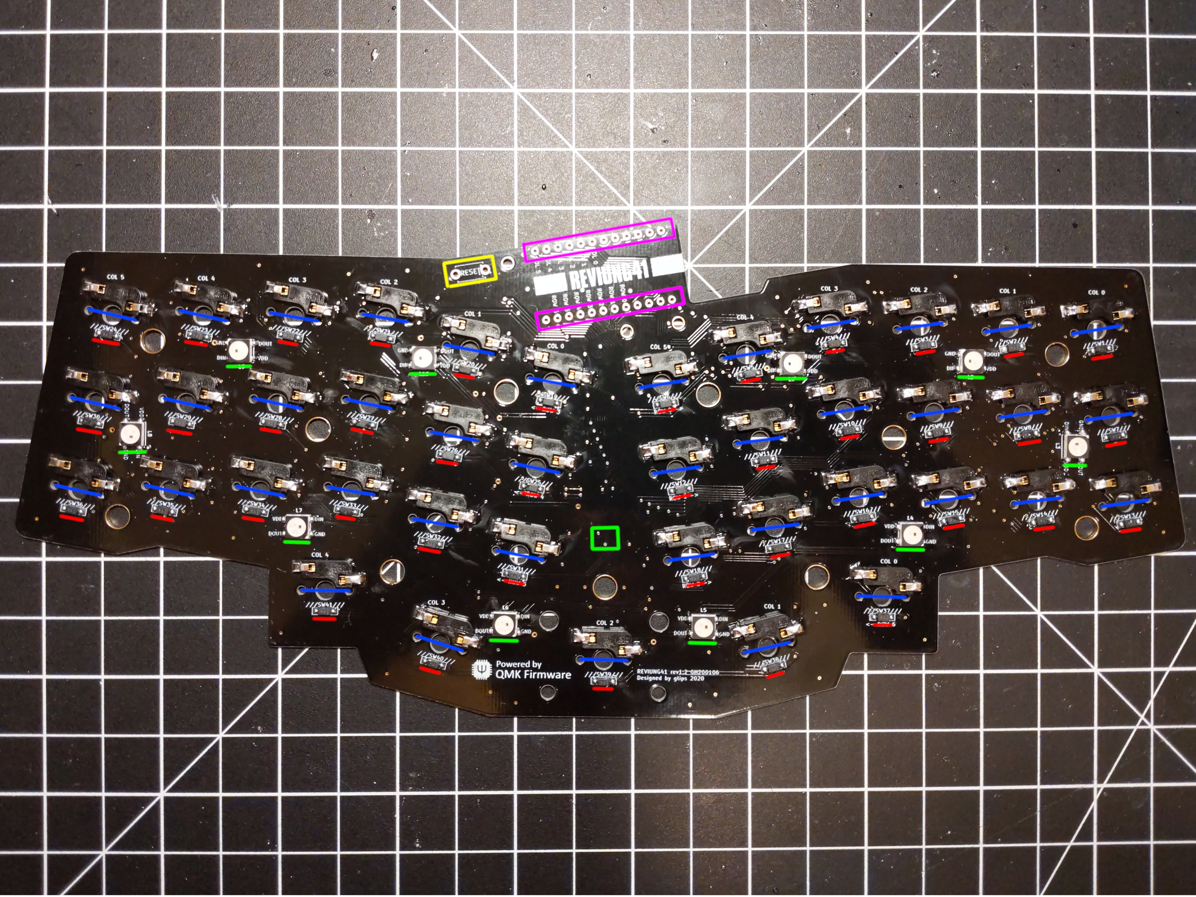
41 diodes are located on the back of the PCB below each switch hole.
10 LEDs are located on the back of the PCB with 1 additional LED on the front of the PCB.
41 sockets are located on the back of the PCB above each switch hole.
The microcontroller socket holes are soldered on the back of the PCB.
The reset button socket holes are soldered on the front of the PCB with the button facing downwards.
Diodes
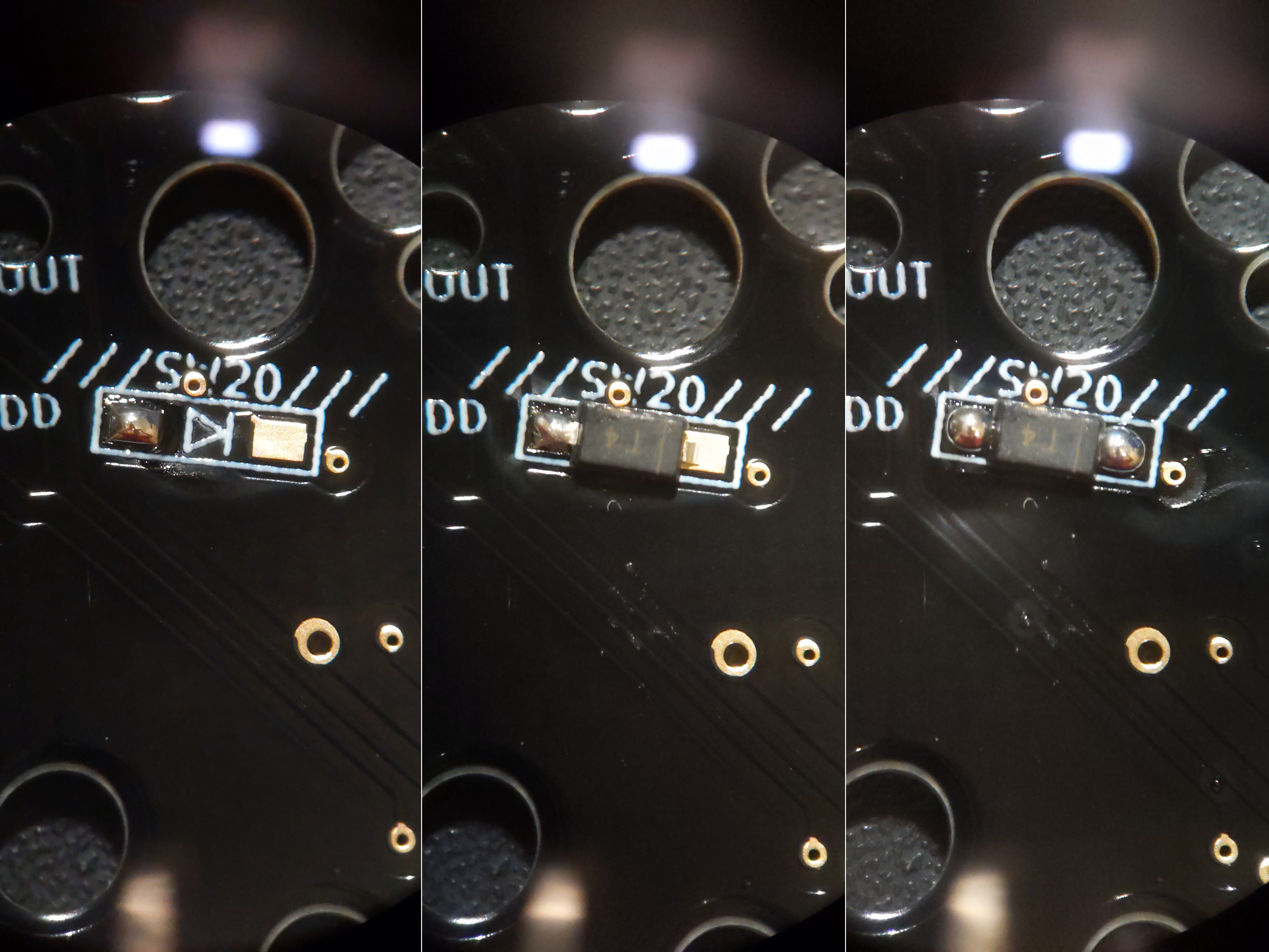
Diodes are soldered to two pads.
Ensure the vertical line on the diode aligns with the vertical line on the PCB!
Tin one of the pads, then hold the iron to the joint while placing the diode leg on the pad. Solder the remaining diode leg to the second pad.
LEDs
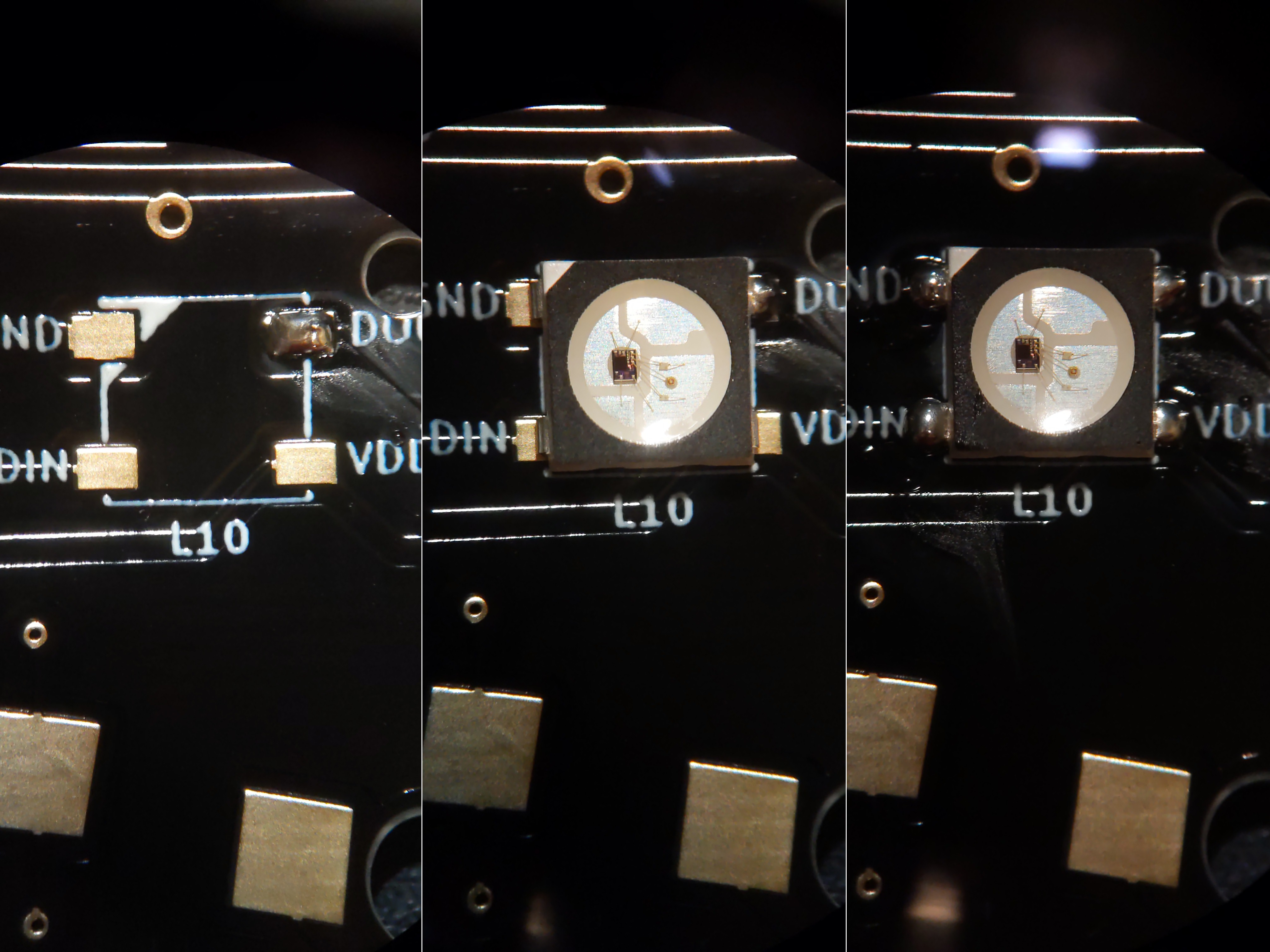
LEDs are soldered to four pads.
Ensure the white triangle on the LED aligns with the white triangle on the PCB!
Tin one of the four pads, then hold the iron to the joint while placing the LED leg on the pad. Solder each remaining LED leg to its respective pad.
Sockets
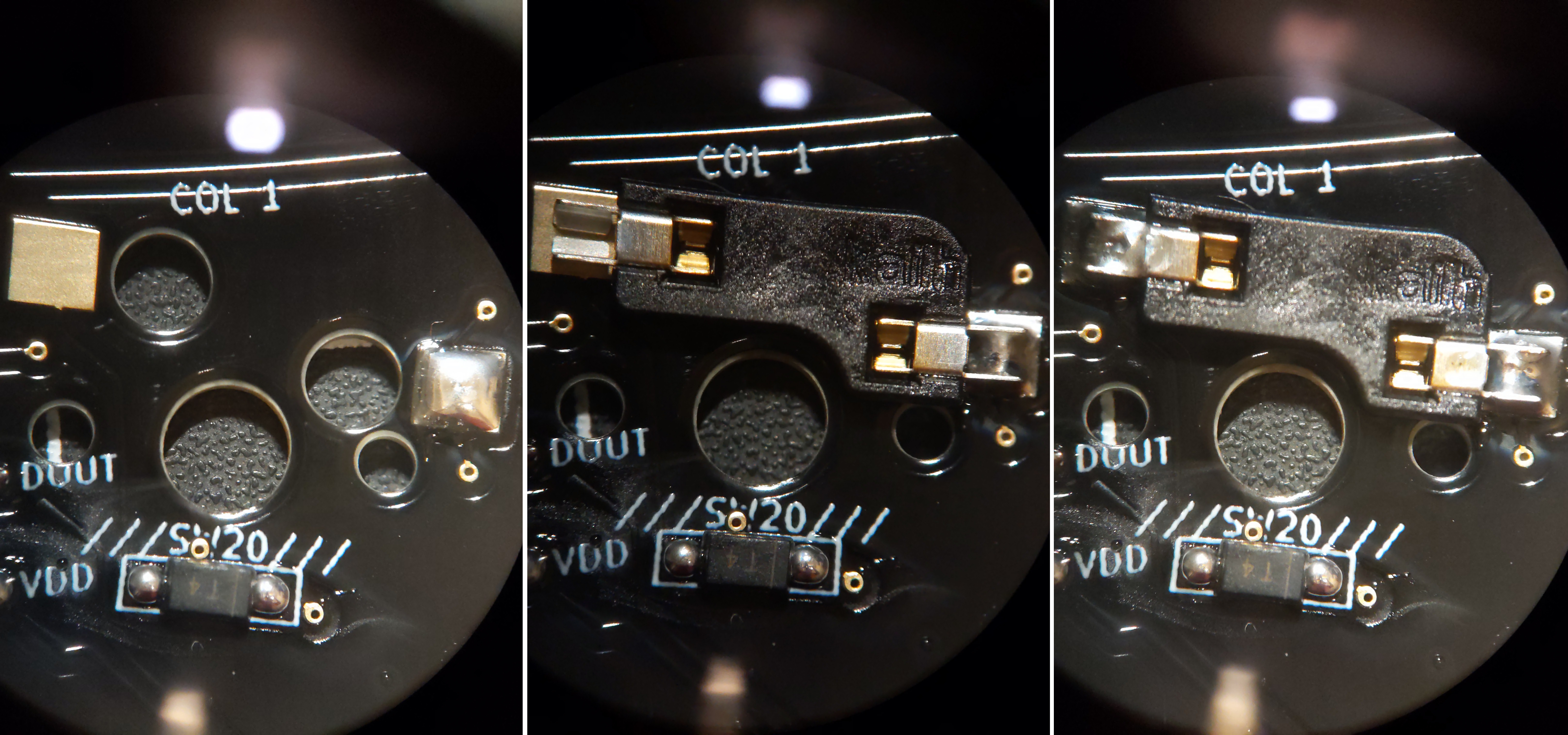
Sockets are soldered to two pads.
Tin one of the pads. While resting the socket leg over the pad, hold the iron to the joint and apply some pressure. Solder will begin to flow through the small crack in the socket leg and bury it in the joint. Apply a generous amount of solder to the second pad. Now that the socket is seated, apply a bit more solder to the first pad.
Microcontroller
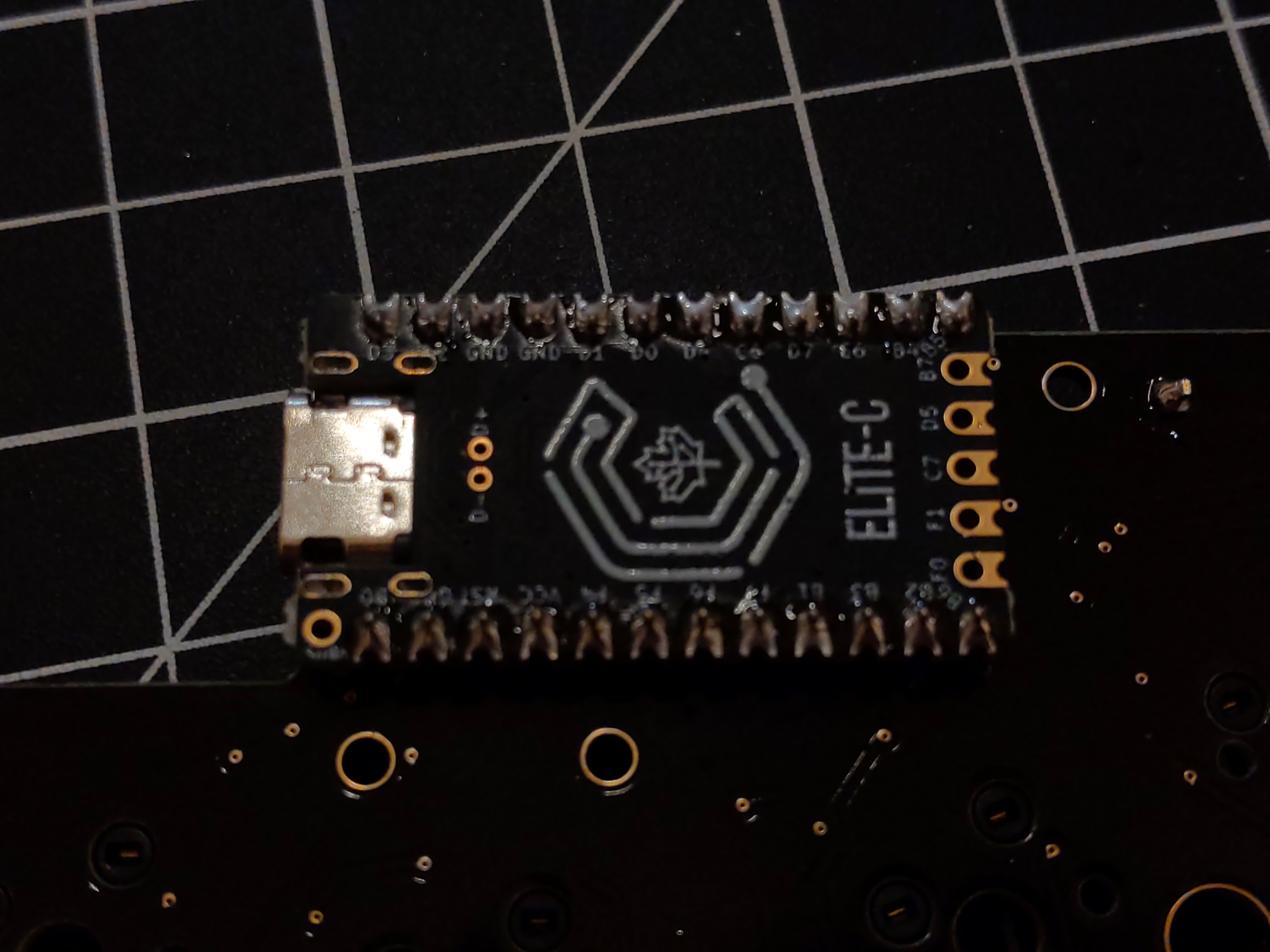
Flash the firmware to verify the microcontroller works before soldering it!
The microcontroller is soldered to spring sockets or pin sockets. Do not use the pins included with the microcontroller.
If using spring sockets, place each row of sockets on the front of the PCB. The microcontroller will be soldered to the sockets.
If using pin sockets, place each row of sockets on the front of the PCB. Flip the PCB over and solder the sockets pin by pin. If the sockets fall out during the process, use electrical tape or similar to secure them from the front of the PCB. Once both rows have been soldered, flip the PCB over again and insert one pin into each socket.
Place the microcontroller face-down on top of the pins/springs. Start by soldering the rightmost and leftmost pins of each row to the microcontroller. Continue to solder each pin ensuring no two joints connect with one another.
The reset button is soldered to the back of the PCB from the front. Place both legs into the holes (the button should friction fit) and solder each leg.
Stabilizer (Optional)

The 2U stabilizer is optional but recommended. Slot the top half of the stabilizer in the mounting hole and screw in the bottom two holes from the back of the PCB.
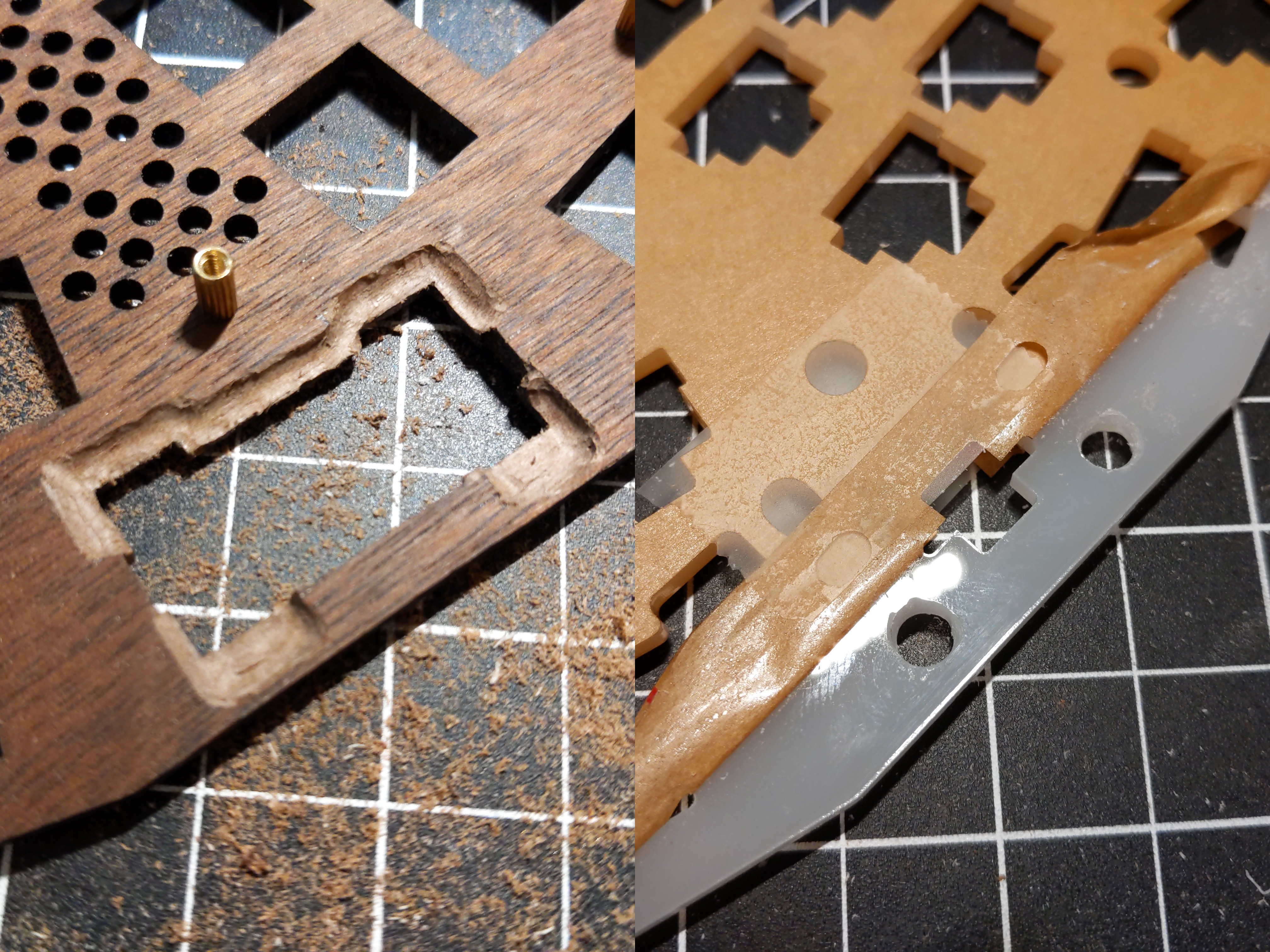
If using non-Cherry stabilizers, some modification may be required!
This build uses Alpaca (Durock) stabilizers which were incompatible. The top plate and middle acrylic required modification.
Plates
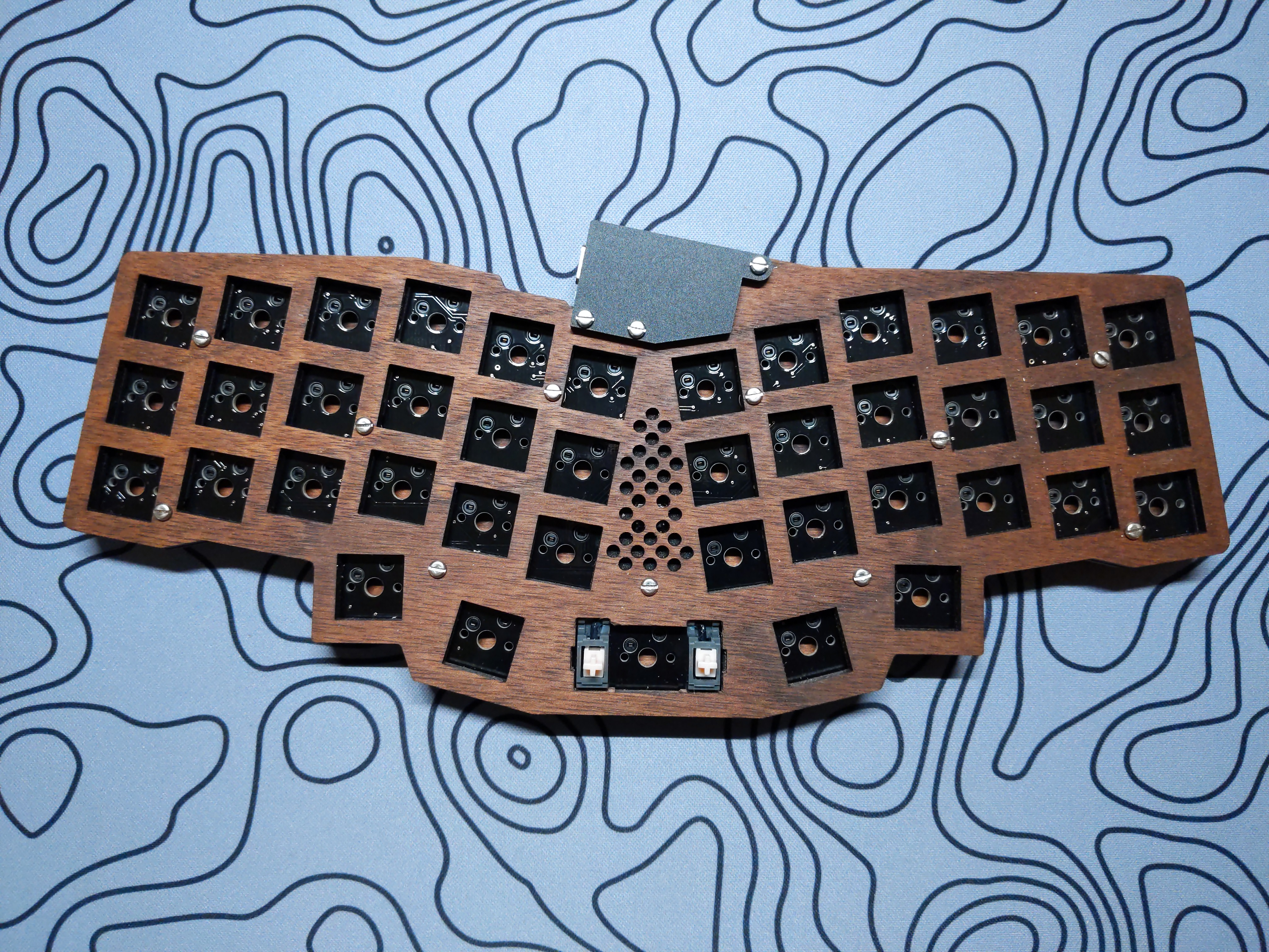
Assemble the keyboard case by placing the PCB between the top and bottom plate and screwing the pieces together. If applicable, insert switch foam between the top plate and front of the PCB and the acrylic layer between the bottom plate and back of the PCB.
Switches
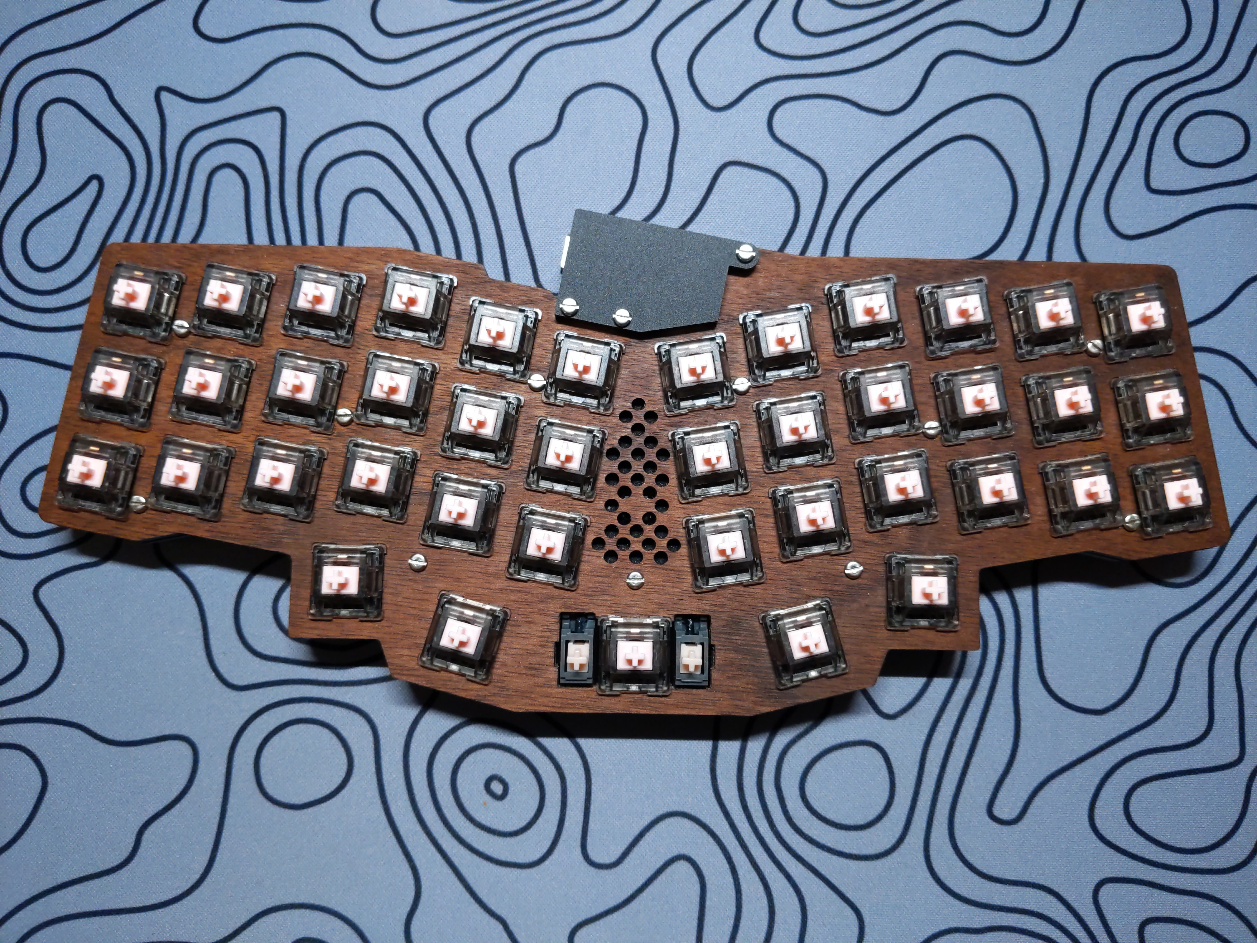
Insert 41 MX-compatible switches into the hotswap sockets.
Firmware
Customization
The easiest way to create a custom keymap is via QMK Configurator, a graphical web-based editor. Advanced users can manually create a keymap to compile and flash with QMK command-line tools.
More information can be found in the QMK Docs or QMK Discord.
Flashing
See QMK Docs: Flashing Firmware for platform-specific instructions.